
Operator`s manual
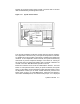
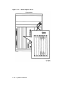
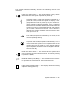

Break enable/disable switch — When this switch is pushed
back (down or O position), breaks are disabled. When it is
forward (up or | position), breaks are enabled. When breaks
are enabled, pressing
Break
on the console terminal halts the
processor and transfers control to the console program. Using
the console command SET CONTROL, you can specify the
control character
Ctrl/C
rather than
Break
to initiate a break
signal.
The break enable/disable switch also controls what happens at
power-on. When breaks are disabled (down or O position), the
system attempts to automatically boot software at power-on.
When breaks are enabled (up or | position), the system enters
console mode (indicated by the >>> prompt) at power-on.
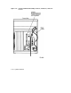
Using the console command SET HALT REBOOT or SET
HALT RESTART_REBOOT, you can set your system to
automatically boot software after the system is halted by
pressing
Break
.
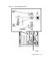
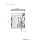
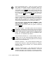
Bus node ID plugs — VAX 4000 systems have two separate
DSSI buses. Two DSSI bus node ID plugs, one for the internal
DSSI bus (Bus 0) and one for the external bus (Bus 1), identify
the bus node to the CPU. These plugs are configured at the
factory. For single-host systems, Bus 0 is identified as Bus
Node 6, Bus 1 is identified as Bus Node 7.
DSSI connectors (DSSI Bus 1) — These two DSSI connectors,
labeled X and Y on the console bulkhead assembly, allow you
to expand your system by connecting additional mass storage
devices to the second DSSI bus.
Ethernet connectors — The console bulkhead assembly has
two Ethernet connectors: a BNC-type connector for ThinWire
Ethernet, and a 15-pin connector for a standard Ethernet
transceiver cable.
Ethernet connector switch — This switch selects either the
ThinWire or the standard Ethernet connection. To use the
standard connection, set the switch to the forward position.
To use the ThinWire cable connection, set the switch to the
1–16 System Overview