
Operator`s manual
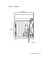
1.2.1.3 System ON/OFF Switch
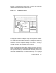
The main system ON/OFF switch is located in the upper left-hand corner
of the front panel (see Figure 1–3). This switch is the power switch for
the entire system.
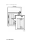
1.2.2 Card Cage
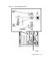
The modules in your system are mounted in a 12-slot card cage behind
the mass storage shelf, as shown in Figure 1–6. The slots are numbered
beginning with slot one next to the power supply.
A console bulkhead assembly with indicators, system controls, and
connectors covers the memory modules and CPU in the first five slots.
1.2.2.1 Memory Modules
The first four slots are reserved for memory modules.
1.2.2.2 CPU
The CPU is in the fifth slot.
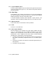
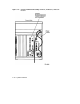
1.2.2.3 Q–bus Option Modules
Slots 6 through 12 are available for Q–bus option modules (see Fig-
ure 1–7). The number and type of modules installed in your system
depend on your configuration. Each Q–bus slot, even an empty one, is
protected by a cover. Together these covers and the console bulkhead
assembly form a shield with a three-fold purpose:
1. To protect external devices from electrical interference generated by
the system, maintaining compliance with FCC and VDE require-
ments.
2. To protect the system from electrical interference generated by ex-
ternal devices.
3. To maintain airflow integrity.
1–10 System Overview