
Operator`s manual


3.2.3 Power Card Assembly
Removal Procedure
Perform the steps in the following procedure to remove the power card
assembly:
1. Turn the main ON/OFF power switch to OFF and disconnect the
power cord from the wall receptacle.
2. Release the two captive fasteners on each side of the bezel that secure
the chassis to the cabinet rails.
3. Remove two 10-32 x 1/2 inch screws from the top of the chassis bezel.
4. Remove two 10-32 x 1/2 inch screws from the bottom of the chassis
bezel.
5. Remove the bezel.
6. Loosen the captive 6-32 x 3/8 inch screw securing each ISE bezel.
7. Remove the ISE bezel and cables.
8. Loosen the two captive screws that secure each ISE device to the
chassis.
9. Remove the ISE device and set it aside on a clear work surface.
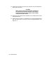
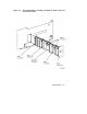
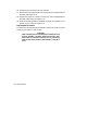
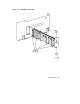
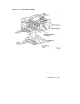
10. Remove the power card connector from the storage backplane assem-
bly (see Figure 3–5).
11. Remove the lower right hand device guide by lifting the front and
then the rear of the slide up (see Figure 3–5).
12. Remove the device guide.
13. Reach into the ISE opening and grasp the power card assembly. Lift
the power card straight up and remove (see Figure 3–5).
Replacement Procedure
To replace the power card assembly, perform the reverse of the actions
in the previous steps in reverse order.
NOTE
After installing the power card assembly in the connec-
tor, dress the cable so that it will be to the right of (be-
hind) the lower right-hand device guide when the guide
is installed.
3–10 Maintenance