
Operator`s manual


16. Pull the chassis forward to the lock position.
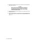
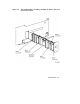
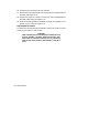
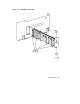
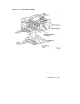
17. Remove the metal plug button from the side of the storage backplane
assembly (see Figure 3–4).
18. Remove the two 6-32 x 3/8 inch screws from the storage backplane
assembly cover panel (see Figure 3–4).
19. Slide the storage backplane assembly through the opening in the
chassis to your right (see Figure 3–4).
Replacement Procedure
To replace the storage backplane assembly, perform the reverse actions
of the previous steps in reverse order.
CAUTION
When installing the storage backplane assembly, be sure
that the assembly is properly aligned to the rails. Also,
ensure that all connector extractors are not interfering
with the side of the chassis as the assembly is pushed in
place.
3–8 Maintenance