
Operator`s manual


3.2.2 Storage Backplane Assembly
Removal Procedures
Perform the steps in the following procedure to remove the storage
backplane assembly from the chassis:
1. Turn the main ON/OFF power switch to OFF and disconnect the
power cord from the wall receptacle.
2. Release the two captive fasteners on each side of the chassis that
secure the chassis to the cabinet rails.
3. Remove two 10-32 x 1/2 inch screws from the top of the chassis bezel.
4. Remove two 10-32 x 1/2 inch screws from the bottom of the chassis
bezel.
5. Remove the chassis bezel.
6. Loosen the captive 6-32 x 3/8 inch screw securing each of the in-
tegrated storage equipment (ISE) bezels (some may be blank bezel
covers).
NOTE
Be sure to note the bus identification number of each
ISE before removing the cover. Each ISE device must
be installed in its correct slot.
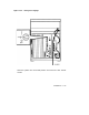
7. Remove the ISE bezels (see Figure 3–2).
8. Disconnect the cable from the bezel.
9. Loosen the two captive screws that secure the ISE device to the
chassis.
10. Remove all ISE devices and set aside on a clear work surface.
11. If a TK70 tape drive is installed, slide the device part way out; reach
in through the top of the chassis and remove the control cable by
pressing the two connector locking tabs. Move the cable to the rear.
12. Slide the TK70 tape drive out and set it aside on a clear work
surface.
3–4 Maintenance