
Operator`s manual


3.2.1 ON/OFF Switch Assembly
Removal Procedure
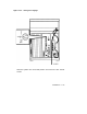
Perform the steps in the following procedure to remove the ON/OFF
switch assembly (see Figure 3–1):
1. Turn the main ON/OFF power switch to OFF and disconnect the
power cord from the wall receptacle.
2. Release the two captive fasteners on each side of the bezel that secure
the chassis to the cabinet rails and pull the VAX 4000 forward.
3. Remove two 10-32 x 1/2 inch screws from the top of the chassis bezel
(see Figure 3–2).
4. Remove two 10-32 x 1/2 inch screws from the bottom of the chassis
bezel.
5. Remove the chassis bezel.
6. Remove the 12 6-32 x 3/8 inch screws securing the top cover to the
chassis.
7. Remove the top cover.
8. Disconnect the plug from the power supply.
9. Using a hex socket wrench, remove two 6-32 hex nuts that secure
the ON/OFF switch assembly to the chassis.
10. Remove the ON/OFF switch assembly from the chassis.
Replacement Procedure
To replace the ON/OFF switch assembly, perform the reverse of the
actions in the previous steps in reverse order.
3–2 Maintenance