
Technical data


c. Remove the bottom door by swinging it out past 90 degrees and
lifting it off the hinges.
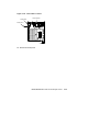
d. To remove the right door latching bracket, remove the three self-
tapping screws and one 6/32 screw. Remove the bracket. Remove
the remaining self-tapping screws (Figure 3–28).
e. To remove the left hinge bracket, remove the five self-tapping screws
(Figure 3–28).
3. Slide the enclosure’s outer shell back and off. Lay the shell and other
hardware aside.
4. Remove the power supply. See Warning Note (Section 3.9).
5. Remove the H3604 console module (BA440 enclosure) or H3602 CPU
cover panel (BA430 enclosure).
a. Release the quarter-turn captive screws (BA430/BA440).
b. Swing open console module and disconnect cables (BA440 enclosure
only).
c. Lift the console module from its hinge pins (BA440 enclosure only).
d. Lay the console module aside (BA440 enclosure only).
e. Disconnect the 50-pin connector cable and lay the H3602 panel
aside (BA430 enclosure only).
6. Remove all module options from the card cage .
7. Remove the SCP (System Control Panel) and its cable.
8. Remove all ISEs and tape drive units from the upper enclosure.
9. Disconnect the extended bus cables from the upper left corner of the
backplane (Figure 3–29).
10. Remove the Vterm regulator module from the backplane (BA440
enclosure only).
11. Turn the enclosure around so that you face the rear panel
(Figure 3–30).
BA430/BA440 FRU Removal and Replacement 3–39