
Specifications


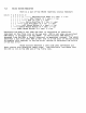


FIBRE
CONTROL
The
fibre
control
re~ister
uses
three
bits.
These
are
write-onl~
si~nals,
and
are
used
by
the
hardware.
XMIT
ON
causes
the
hardware
to
li~ht
the
LED
at
the
Mother
Board
end
of
the
fibre
link.
The
other
two
signals
are
dia~nostic
signals.
bit
t
765
432
1 0
1 ,----
Xmit
On
(0
=
nO,
1 =
yes)
,----
Maintenance
Mode
(0
=
no,
1 =
~es)
,----
Force
CRC
Error
(0
=
no,
1 =
~es)
,----
Unused
,----
Unused
,----
Unused
,----
Unused
,----
Unused
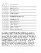
The
followins
bit
patterns
are
defined:
Xmit
On
J
Maintenance
Hade
I
Purpose
--------I--------------------I--~--------------------
o I 0 I
Powerup
State
--------1--------------------1-----------------------
o I 1 I
Electrical
Loop-Back
--------1--------------------1-----------------------
1 I 0 I
Normal
Operation
--------I~-------------------I-----------------------
1 I 1 I
Optical
Loop-Back
--
______
1
______
--------
______
1
______
-----------------
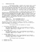
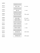
7.8.4
68000.
B~te
1
B~te
3
B~te
5
B~te
7
USART's
(Motorola
2661
EPCI's)
Each
USART
has
four
resisters
that
are
accessible
b~
the
The
map
is
as
followsl
Holding
ReSister
Status
Register
Mode
Resisters
Control
Resister
The
first
time
one
writes
to
B~te
5,
one
accesses
Mode
ReSister
O.
Thereafter,
an~
reference
to
B~te
5
refers
to
Mode
Re~ister
1.
B~te
1
refers
to
the
Transmit
Holdins
Register
or
the
Receive
Holding
Resister,
dependins
on
whether
one
is
performing
a
read
or
write
operation.
7.8.5
CRT
CONTROLLER
The
CRT
Controller
is
two
b~tes.
B~te
1
is
the
address
pointer.
Byte
2
is
the
data
resister.
You
must
write
the
value
of
the
resister
~ou
wish
to
write
to
into
the
address
pointer
before
writins
the
desired
value
of
that
reSister
into
the
CRTC's
data
resister.