
Specifications

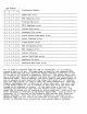

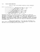


LED
Number
Dia~nostic
Reason
3
2 1
o
---------~~---~
---------~--------~-~---------------~-----------~-------
o I 0 I 0 1
68000
CPU
error
---1---1---
--------------------------------------------------------
o I 0 I 1 0
ROM
Checksum
error
---1---1---
--------------------------------------------------------
o I 0 1 1 1
Pro~ram
RAM
error
---1---1---
--------------------------------------------------------
o I 1 I 0 0
CRTC
Re~ister
error
---1---1---
--------------------------------------------------------
o 1 1 I 0 1
Tablet
Port
error
---1---1---
---1--------------------------------------------------------
Q I 1 I 1 0
Ke~board
Port
error
---1---1---
--------------------------------------------------------
o I 1 I 1 1
Fibre
Optics
Loop-Back
error
---1---
--------------------------------------------------------
1 I 0 0 0
Vs~nc
Time-Out
error
---1---
--------------------------------------------------------
1 I 0 0 1
Frame
Buffer
error
---1---
--------------------------------------------------------
1 1 0 1 0
BBA
Scratchpad
error
---1---
--------------------------------------------------------
1 I 0 1 1
BBA
Command
error
---1--- ---1---
--------------------------------------------------------
1 I 1 0 I 0
Tablet
ID
error
---1--- ---1---
--------------------------------------------------------
1 I 1 0 I 1
Tablet
Self-Test
error
---1---
---1---
--------------------------------------------------------
1 I 1 1 1 I 0 I
Ke~board
ID
error
---1---1---1---1--------------------------------------------------------
1 I 1 I 1 I 1 I
Ke~board
Self-Test
error
___
1
___
1
___
1
___
1
______
--------------------------------
_________________
_
·0·
is
used
to
indicate
that
the
LED
is
turned
off;
·1·
is
used
to
indicate
that
it
is
on.
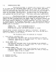
The
same
code
is
used
for
the
Ke~board
LEDS,
Mother
Board
LEDS
and
Ho~t
Interrupt
Reason
Re~ister
(with
bits
14
and
15
turned
on
to
indicate
a
dia~nostic
failure>.
The
Mother
Board
also
has
a
~reen
LED,
which
is
used
to
indicate
the
mode
that
the
machine
is
operatin~
under.
Durin~
Powerup,
the
error
code
on
the
Mother
Board
is
set
in
advance
of
each
test
with
the
~reen
LED
turned
off
to
indicate
that
the
test
failed
(in
case
it
does
not
reach
completion).
Once
the
Powerup
confidence
test
is
done
and
we
enter
Idle
Loop,
the
error
code
on
the
Mother
Board
is
set
in
advance
of
each
test
with
the
~reen
LED
turned
on
to
indicate
no
errors.
If
the
test
finds
a
failure,
it
repl~ces
the
same
error
code
with
the
Powerup
error
code;
i.e.,
the
~reen
LED
is
turned
off
to
indicate
an
error
condition.
Onl~
the
first
error
detected
is
reported
to
the
Hother
Board
LEDS.
Once
an
error
is
detected,
it
is
reported
to
the
Ke~board
LEDS
and
the
Host
Interrupt
Reason
Re~ister.
Onl~
the
first
error
detected
is
reported
to
the
Ke~board
LEDS,
but
all
errors
are
reported
to
the
Host
(includin~
bit
14
set
to
indicate
error
durin~
Idle
Loop
yersu~
Powerup
failure>.