
Specifications

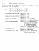


5.1.4.
I/O
REGISTERS
The
follo~in~
devices
are
mapped
into
the
I/O
space
(addr
23
=
1)
of
the
HC68000
cPu:
Tablet
USART
Keyboard
USART
Mouse
position
re~ister
Crt
controller
resister
System
status
resister
test
led
resister
BBA
ISOI
f/f
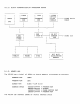
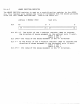
CRT
controller
resister
The
CRT
controller
provides
the
necessary
timins
sisnals
to
the
VR100
monitor,
and
the
address
for
the
start
of
the
visible
screen
memory
that
will
be
read
out
seauentially
durins
refresh
of
the
screen.
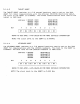
The
CRT
controller
has
two
memory
addresses
assiSned
in
the
I/O
space.
The
first
is
a
pointer
reSister
that
is
loaded
with
the
value
of
the
reSister
that
data
will
be
deposited
in.
Their
are
14
resisters
available
for
use
in
the
CRT
controller.
The
second
resister
is
the
data
resister.
Any
data
deposited
in
the
data
resister
will
be
transfered
to
the
resister
pointed
to
by
the
address
resister.
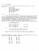
BIT
eTRC
ADDRESS
REGISTER
address
=
8000AO
(HEX)
CRTC
DATA
REGISTER
address
=
BOOOA4
(HEX)
7 6
5
4
write
only
read/write
3 2 1
o
I
D7
I
D6
I
D5
I
D4
I
D3
I
D2
I
D1
I
DO
I
REFER
TO
DEC.
SPEC.
A-PS-16963-00
FOR
MORE
DETAILED INFORMATION
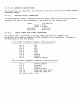
The
reauired
parameters
for
proper
operation
of
the
VR100
monitor
at
a
screen
resolution
of
1088
Horz
x
960Vert
pixels
are:
RO
=
4S
R1
=
34
R2
=
37
R3
=
06
R4
=
74
RS
=
05
R6
=
72
R7
=
72
R8
=
00
R9
=
11
RiO
=
00
Rl1
=
00
R12
=
00
R13
=
00
R14
=
00
R1S
=
00