
Specifications


7.0.1
7.0.2
7.0.3
POWERUP
SELF-TEST
Tests
occur
in
order
of
increasins
lo~ic
complexit~,
in
order
to
maximise
error
detection
and
minimise
the
chance
of
a
catastrophic
s~stem
failure.
The
68000
remains
at
prioritw
level
seven
(all
maskable
interrupts
disabled)
until
all
liD
control
chips·
have
been
tested
and
initialised.
At
this
point,
the
priQrit~
level
is
lowered
to
zero
(all
maskable
interrupts
enabled)+
The
Power~p
code
should
run
less
than
twenty
seconds;
the
expected
cold-start
warm-up
time
for
the
monitor.
The
Keyboard's
70-millisecond
Self-Test
runs
in
parallel,
but
is
under
the
control
of
the
Ke~board'$
central
processin~
unit.
At
the
end
of
Powerup
Self-
Test,
one'of
two
icons
is
displa~ed
on
an
otherwise
white
screen:
1.
House
LOSin
Icon
2.
S~stem
Failure
Icon
displa~ed
if
there
were
no
Poweru?
errors.
displayed
if
there
were
Powerup
errors.
In
addition,
the
ke~board's
bell
is
runS
when
the
Mous~
LOSin
Icon
is
displa~ed,
to
let
the
user
know
that
the
terminal
is
ready
for
normal
operation.
Lo~ins
are
disabled
if
there
were
errors
on
Powerup,
but
are
not
disabled
if
errors
are
found
durins
Idle
Loop.
Once
the
user
hits
a
mouse
button
to
losin,
however,
there
is
the
chance
that
the
link
may
be
down
or
may
So
down
while
transmittins
the
mouse
event
to
the
host.
In
this
case,
the
Mouse
LoSin
Icon
is
replaced
by
a
third
icon;
the
Link
Down
Icon.
Whenever
this
icon
appears
on
the
screen,
it
is
UP
to
the
host
to
reinitiate
communication
with
the
terminalt
The
Powerup
code
is
structured
so
that
confidence
is
built
hierarchicall~.
Each
procedure
first
checks
the
error
flas,
and
skips
over
the
diaSnostic
portion
if
there
were
an~
previous
errors
(onl~
the
first
detected
error
is
reported,
and
further
initialisation
functions
only
to
enable
entrance
to
Maintenance
Mode).
Tests
are
executed
in
the
followins
order:
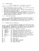
A.
SIZE
contained
in
the
F/W
roms
appr
6kb
B.
OPERATION
on
power-up
of
the
sYstem,
the
u-diasnostics
will
perform
a
self
test
of
the
mother
board,
BBA
board,FOT/R
board,the
fiber
optic
link
and
the
UBW
board.
The
test
cove
raSe
is
)80%.
Errors
will
be
reported
b~
means
of
the
leds
located
on
the
rear
of
the
mother
board,
and
reported
to
the
host
CPU
if
possible.
on
successful
completion
01
the
power-up
tests,
the
GREEN
led
on
the
motherboard
will
be
lit,
and
the
u
diaSnostics
will
enter
IDLE
self
test
until
the
user
presses
a
mouse
button.
DC
POWER
SUPPLY
When
power
is
initiallY
applied
to
the
Mother
Board,
an
internal
RESET L
siSnal
provides
a lOOms RESET
si~nal
to
initialise
the
hardware
to
a
known
state.
If
the
H7862
Power
Supply
volta~es
are
not
within
tolerances
(DC
OK
neSated),
RESET L
will
be
held
true;
thereb~
preventinS
the
microcode
from
startins.
The
RESET L
sisnal
turns
all
five
Mother
Board
LED's
(1
Green,
4
Red)
on,
which
provides
a
test
of
the
LED's
themselves.
~t
the
end
of
RESET L
(nesated),
the
Pow~~up
code
blinks
the
LED's
off
and
on
asain
once.
This
action
also
causes
the
state
seauencers
to
remap
ROM
from
$000000
to
$180000.
MOTOROLA
68000
MICROPROCESSOR