
Specifications


5.
HARDWARE
5.1
DISPLAY
PROCESSOR
BOARD
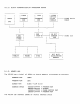
5.1.1
DESCRIPTION
The
dis?la~
processor
module
(DPM)
in
the
VS100
contains
the
MC68000
cpu,pro~ram ram,pro~ram
rom,
screen
ram,and
1/0
ports.
Connected
to
the
displa~
processor
module
as
dau~hter
boards
are
the
fiber
optic
transmitter/reciever
(FOT/R)
module
and
the
Bit
Blit
Accelerator
(BBA)
module.
The
timin~'for
the
DPM
is
derived
from
a
79.96Mhz
ECl
oscillator
and
divided
down
to
40Mhz,
20Mhz,
10Mhz
and
other
lower
freQuencies
for
use
in
the
s~stem.
The
80Mhz
clock
allows
for
a
screen
displa~
of
1088
pixels
horizontall~
by
864
pixels
vertically.
Communication
with
the
host
cpu
(VAX11/7xx)
is
thru
a
fiber
optic
cable
af
UP
to
300
meters
in
len~th,
which
connects
to
the
Unibus
Window
Module
(UBW)
located
in
the
VAX
unibus
backplane.
The
fiber.optic
interface
operates
at
a
10Mhz
rate.
All
transmissions
across
the
fiber
optic
cable
are
initiated
by
the
DPM's
68000
cpu
or
by
the
BBA
module.
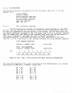
Transmissions
to
the
VAX
cpu
are
54
bits
in
len~th
(16
data
bits,
16
crc
bits,
18
address
bits,
1
control
bit,
3
spare
bits).
Recieved
data
from
the
VAX
cpu
is
24
bits
in
lensth.(16
data
bits,
1
control
bit
and
7
spare
bits).
Data
is
transfered
across
the
fiber
link
in
a
BI-PHASE
l
encodin~
scheme.
All
data
transmissions
are
sent
with
a
16
bit
CRC
checksum.
The
DPM
also
contains:
a
proSrammable
CRTC
controller
for
~eneratin~
the
necessary
timin~
siSnals
for
the
VR100
monitor
two
pro~rammable
USART's
for
communication
with
the
optional
diSitizins
tablet
and
the
LK201Cx
keyboard.
A
discrete
interface
for
the
VS10X-EA
hand
held
mouse
A
set
of
5
lED's
for
fault
indication.
4
led's
are
red,
and
1
led
is
Sreen.
The
led's
are
located
on
the
rear
of
the
DPM,
and
are
viewable
from
the
rear
of
the
multibox.
A
power-up
self
test
diasnostic
used
for
testins
of
all
major
portions
of
the
DPM
module,
the
BBA
module,
the
FOT/R
module,
and
the
LK201Cx
keyboard.
An
extended
set
of
tests
ar~
provided
for
user
tests
of
the
VS10X-EA
hand
held
mouse,
the
VS10X-BA
disitizins
tablet,
and
aliSnment
of
the
VRI00
monitor.
llde
loop
self
test
that
will
run
continuoslY
after
power-up
self
test
is
run,
but
before
the
user
loSs
onto
the
VAX
cpu.
Idle
self-test
provide
a
continuous
check
of
the
functionalit~
of
the
VS100.
The
Micro-diasnostics
also
has
a
MAINTANCE
MODE
which
will
enable
the
user
to
run
specific
tests
and
to
test
the
1/0
devices.