
Specifications


5.6.8
FAULT
INDICATING
L.E.D.S
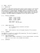
The
VR100
monitor
is
eauiped
with
4
fault
indicatins
LEDs.
These
LEDs
are
normall~
illuminated
to
indicate
the
presence
of
the
necessar~
sisnals/voltases
for
the
proper
operation
of
the
monitor.
The
LEDs
indicate
the
followin~
conditions:
VIDEO
HORZ
SYNC
VERT
SYNC
B+
Volta~e
minimum
threshold
of
300MV
reauired
TTL
level
reBuired
TTL
level
reauired
80X
of
reQuired
B+
level
for
no~mal
operation
of
the
monitor
is
available
fi~ure
of
back
panel
T.B.S.
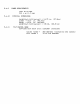
POWER
REQUIREMENTS
115v
@
lamp.
240v
@
.Samp
fuse
t~pe
=
3AG
(U.S.)
5mm
X 20mm (EUROPEAN)
CONTROLS,EXTERNAL
INPUTS
brishtness
contrast
The
inputs
to
the
VR100
monitor
are
SNC
t~pe
connectors,
located
on
the
rear
panel
of
th~
monitor.
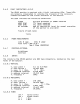
5.6.8.1
VERTICAL
V.
s~rlc
width
=
V.
sync
period
=
V.
s~nc.
Tr
=
<3ns.
V.
blankins
interval
V.
unblank
interval
V. f
reatJenc~
=
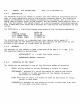
5.6.8.2
HORIZONTAL
H.
s~nc
width
=
H.
sync.
period
=
H.
sync.
Tr
=
<3ns.
H.
blankinS
interval
H.
unblank
interval
H.
freatJenc~
=
5.6.8.3
VIDEO
0.1
to
0.5
Msec
16.667
Hsec
Tf
=
<3ns.
0.775
Hsec
15.912
Hsec
60Hz.
2-8
uSEC
18.416
uSEC
Tf
=
<3ns.
4.804
IJSEC
13.612
uSEe
54.3KHz.
Voh =
Vol
=
Tr
=
Tf
=
(white
level>
(black
level)
-(
3ns.
-(
3ns.