
Specifications

5.4
FIBER
OPTIC
TRANSMITTER/RECEIVER
MODULE
(DEC.t
54-16010)
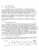
FUNCTIONAL
DESCRIPTION
The
fiber
o~tic
transmitter/receiver
module
is
used
to
drive
the
fiber
o~tic
cable.
The
data
in~uts
to
the
module
are
ECl
level
sisnals.
the
data
outputs
from
the
module
are
Eel
level
si~nals.
Also
out~ut
from
the
module
is
the
link
available
si~nal,
used
to
indicate
that
the
lisht
received
is
above
a
minimum
value
as
determined
b~
the
sauelch
circuitr~.
NOTE:
the
link
available
sisnal
assereted
indicates
that
lisht
is
beins
received.
It
does
not
mean
that
the
fiber
optic
link
is
functional.
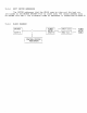
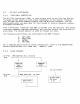
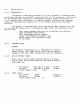
BLOCK
DIAGRAM
FIBER
CABLE
---------
------------
(receive)
----)IPIN
1------)1
h~brid
I
diode
I I
receiver
1-----------)
ECl
DATA
OUT
1
sauelch
1-----1
link
1-----)
link
------------
I
available
1
available
ECl
DATA
IN-----)I
driver
1-----)1
L.E.D.
1------)
FIBER
CABLE
(trasmit)
the
FOT/R
has
four
sections.
These
are:
1.
the
h~brid
receiver,
2.
the
sauelch
circuit,
3.
the
link
available
circuit
and
4.
the
transmit
L.E.D.
driver.
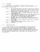
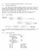
SIGNAL
DESCRIPTION
40
pin
corlnector,
Female
----~-~------~-----------~--~---
pins
1,2,3,4
+5v
~irls
5,6,11,12,
SNIt.
29,30,32,33,
34,36,37,38,
40
pins
7,8,9,10
+12v
pins
13,14,15,16
-12v
pins
17,18,22,
N.C.
23,24,25,26,
27,28
pin
19
link
avail
H
pin
20
link
avail
L
pin
21
~<mi
t
on
H
pin
31
ecl
t}~
data
l
pin
35
ecl
t>~
data
H
pin
39
ecl
bip
data
l