
Specifications
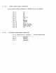
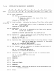
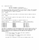

CSR 0
CONTROL/STATUS
RESISTER
BIT
ASSINGMENTS
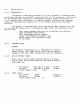
15
14
13
12
11
10
9 8
7 6 5 4
---
1 0
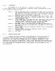
I
LT
I
LA
I LE I
XO
I
MM
I
CD
I
MD
IRES.I
OWN
IRES.I
IE
I
FUMCT
I
GO
,
BIT
15
Link
Transtition
set
when:
1.
a
link
error
occurs
2.
there
is
a
chanse
in
the
state
of
the
link
available
bit
cleared
b~:
The
host
CPU
BIT
14
Link
Available
circuitr~
indicates
the
status
o~
the
fiber
cable
sauelch
set
when:
a
suf~icient
level
of
liSht
is
detected
b~
the
fiber
o2="tic
receiver
cleared
b~:
The
host
CPU
BIT
13
Link
Error
set
when:
a
CRC
error
is
detected
b~
the
fiber
o2="tic
receiver
durins
data
reception
cleared
b~:
cleared
when
the
host
cpu
clears
bit
15
BIT
12
Xmitter
On
used
to
control
the
state
of
the
Fiber
Optic
PIN
transmitter
diode
set
to
1 =
lisht
on
cleared
to
0 =
lisht
off
BIT
11
Maintance
Hode
controls
the
state
of
the
U.B.W.
module.
Allows
data
to
be
looped
back
internall~
to
the
module
for
testins
purposes.
set
to
al
=
maintance
Dode
enabled
cleared
to
0 =
normal
operation
of
the
module
BIT
10
Crc
Disable
used
b~
diasnostics
to
disable
the
Sene
ration
of
CRC
checksums.
BIT
9
BIT
a
BIT
7
BIT
6
BIT
5
set
to
1 =
disable
CRC
Seneration
cleared
to
0 =
enable
CRe
generation
Maintance
Done
used
to
siSnal
the
end
of
a
maintance
mode
c~cle
set
to
1
=
Iflaintance
mode
c~cle
done
cleared
to
0
=
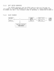
J;~ESERVED
OWN
I
nte
r
rl.Jpt
Erlable
RESERVEII
BIT
4-1
FUNCTION
CODE
specifies
an
operation
to
be'
performed
b~
the
displa~
processor.
BIT 0
GO
bit