
Specifications


5.1.5
I/O
CONNECTOR
DESCRIPTIONS
The
followin~
1/0
connectors
are
located
on
the
rear
panel
of
the
VS100 DISPLAY
PROCESSOR
MODULE.
MONITOR
OUTPUT
CONNECTORS
The VR100
monitor
uses
3
seperate
outputs.
Thes~
outputs
are
provided
throu~h
isolated
BNe
t~pe
50
ohm
connectors.
The
levels
of
the
outputs
are:
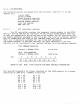
video
black
white
horz.s~nc
vert.s~nc
0.Ov-800
my.
= O.Ov
=
0.700v
0.4v-2.4v
0.4v-2.4v
TABLET
POWER
AND
SIGNAL
CONNECTORS
The
tablet
uses
2
connectors.
one
for
power
and
one
for
si~nals.
The
connectors
are
industr~
standard
D-SUB
miniature
t~pe
connectors,
located
on
the
backpanel
of
the
DPM
module.
9
pin
power
connector
(female,
D-sub
miniature)
pin
1 +5v
pin
2
+5v
pin
3
N.C.
pin
4
+12v
pin
5
N.C.
pin
6
-12v
pin
7
SroJ.Jrcd
pin
8
sround
poin
9
chassis
S
rOI.Jnd
25
pin
sisnal
connector
(female,
D-sl.Jb
IJtiniature)
poin
1
safet~
Sround
pin
2
transmit
pirJ
3
receive
pirl
7
s i Srlo 1
Srour.d
pin
12
reserved
(test
INIT)
pin
13
reserved
(test
OK
)
all
other
poins
=
n.c.