VAXSTATION 100 ENGINEERING SPEC REV 0.1 15 MARCH 1983 15 JUNE 1983 1. OVERVIEW The VS100 workstation is a 19- monochrome workstation desi~ned for the professional user. The VS100 consists o~ a corporate standard multibox containin~ an H7865 power suppl~,display processor module,a fiber optics transmitter/receiver module and a bitblit accelerator module. The VS100 uses a 19 in monitor (VR100) in a landscape format. The monitor has a screen resoultion of 1088 pixel horizontall~ by 864 pixels verticall~.
4.4 ACOUSTIC NOISE DIN 45635 PTl and PT16 - Measurement of airborne noise emmited by machines VDE2058 Part 2 DEC.std. 102, section 4 will supercede the above available 4.5 ~uidelines when ERGONOMICS ZN1/535 - Er~onomics reauirements for display workstations in the office enviroment. 4.6 ENVIRONMENT DEC.std. 102 - Environment standard fo? computers and peripherals ( class S, with operatin~ temperature ranSe of 10 to 40 desrees C and 10 to 90 percent relative humidity). 4.7 LANGUAGE DEC.std.
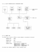
5. HARDWARE 5.1 5.1.1 DISPLAY PROCESSOR BOARD DESCRIPTION The processor module (DPM) in the VS100 contains the MC68000 rom, screen ram,and 1/0 ports. Connected to the displa~ processor module as dau~hter boards are the fiber optic transmitter/reciever (FOT/R) module and the Bit Blit Accelerator (BBA) module. The timin~'for the DPM is derived from a 79.96Mhz ECl oscillator and divided down to 40Mhz, 20Mhz, 10Mhz and other lower freQuencies for use in the s~stem.
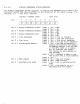
5.1.2. BLOCK DIAGRAM,DISPLAY PROCESSOR BOARD ------.----- --------128Kb 16Kb I I I I IPROGRAMI RAM I I f I 68000 --------IPROGRAMI ROM I I ---- ...
.1.4. I/O REGISTERS The follo~in~ HC68000 devices are mapped into the I/O space (addr 23 = 1) of the cPu: Tablet USART Keyboard USART Mouse position re~ister Crt controller resister System status resister test led resister BBA ISOI f/f CRT controller resister The CRT controller provides the necessary timins sisnals to the VR100 monitor, and the address for the start of the visible screen memory that will be read out seauentially durins refresh of the screen.
DISPLAY PROCESSOR STATUS REGISTER The DISPLAY PROCESSOR STATUS re~ister is used by the MC68000 CPU to obtain the status df events the have an effect on the operation of the VS100 system. This resister is a 'read only' resister. = 8000CO address bit 7 6 5 read only (HEX) 4 3 2 1 o I D7 I D6 I D5 I D4 I D3 I D2 I D1 I XX I bit 7 bit 6 bit 5 bit 4 = mouse = = = bit :3 = bit 2 = pushbuttonfriSht. losic losic ITIOIJSe pushbuttonfmiddle. losic loSic mOt.Jse pl.
MOUSE POSITION REGISTER The MOUSE POSITION reSister is used as a count/direction resister by the 68000 cpu. This reSister will contain the value of increments that the mouse was moved since the last ·MOUSE POSITION REGread by the 68000 cpu. address 15 bit = 800060 read only (HEX) 8 o 7 I Y7 ---------------------- YO I X7----------------------- XO I -----------------------------------------------~------ --------- bit 15 = Y7 The M.S.B. of the Y position reSister.
TEST LEDS REGISTER The TEST LED's re~ister is used to turn on/off the 4 red led's and 1 ~reen led located on the rear of the DPM board. These LED's are used by the microdiagnostics to indicate failure of any of the major sections of hardware in the VSi00 system. address 7 BIT = 6 800080 (HEX) 5 4 WRITE ONLY 3 2 1 o I XX I XX I OK I G5 I R3 I R2 I Rl I RO I bit 7 = RESERVEII bit 6 = RESERVED bit 5 = TEST OK bit 4 = greer. led bit 3 = red led 3 Used in the manufacturing enviroment.
TABLET USART The TABLET USART re~ister is 4 1/0 mapped locations used to set-up the 2661 USART for proper communications with the optional VS10X-BA di~itizin~ tablet. The clock to the USART is 5.000Mhz. The normal communications baud rate to the tablet is 9600 baud address = 7 6 BIT 800020 800022 800024 800026 5 (HEX) (HEX) (HEX) (HEX) REAII/WRITE REAII/WRITE REAII/WRITE REAII/WRITE 3 4 2 0 1 I II7 I D6 I II5 I II4 I D3 I D2 I Dl I DO I REFER TO IIEC.SPEC.
5.1.5 I/O CONNECTOR DESCRIPTIONS The followin~ 1/0 connectors are located on the rear panel of the VS100 DISPLAY PROCESSOR MODULE. MONITOR OUTPUT CONNECTORS The VR100 monitor uses 3 seperate outputs. Thes~ outputs are provided isolated BNe t~pe 50 ohm connectors. The levels of the outputs are: video throu~h 0.Ov-800 my. O.Ov black = white = 0.700v horz.s~nc vert.s~nc 0.4v-2.4v 0.4v-2.4v TABLET POWER AND SIGNAL CONNECTORS The tablet uses 2 connectors. one for power and one for si~nals.
MOUSE POWER/SIGNAL CONNECTOR 15 pin power/si~nal pin pin pin Frin pi r. pin pin pin ?'in pin ?'in pin pin pirl pin 5.1.5.4 1 2 3 4 5 6 7 8 9 10 11 12 13 14 15 connector (female, D-sub miniature) YA YB XB XA N.C. +5V D.C. N.C. N.C. GROUND GROUND N.C. RIGHT BUTTON MIIIDLE BUTTON LEFT BUTTON N.C.
INTERRUPTS The MC68000 uP on the DPM has 7 levels of interrupt. Level 7, the hiShest level is non-maskable. Interrupt vector addresses are fixed. The 7 levels of interrupt are: level 7 = level 6 = level 5 = level 4 = level 3 level 2 = = level 1 = BBA non-existent memory. Set when the BBA tries to address non-existent memor~ in the VAX cpu. Cleared by clearins the BBA 'So' bit.< the BBA will then clear its memor~ reauest, which will clear the LEVEL 7 interrupt. VERTICAL SYNC.
5.2 UNIBUS WINDOW MODULE 5.2.1 FUNCTIONAL DESCRIPTION The M7452 module is a standard hei~ht hex size module used as an interface between the VS100 and the VAX11/7XX cpu. The module connects to the VAX unibus backplane and recieves its power from the VAX. The M7852 is connected to the VS100 b~ a 2 channel fiber optic cable. The M7452 has 8-16 bit re~isters used for the transfer of data between the VS100 and the VAX cpu. The VAX is allowed to address the control/status re~isters onl~.
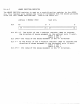
SOFT VECTOR ADDRESSES The VECTOR addresses that the VS100 uses to interrupt the host cpu are loaded b~ the DEVICE DRIVER prior to ucode load. The vector address must be loaded into CSR 7. The allowable ranse of addresses is OOOOOO-001776(BASE 8) BLOCK DIAGRAM IUNIBUS I I FIBER t ---IXMIT S.R.I---) ,I<--------~------------>I OPTIC 1(-)1 1---------1 IXCVRIS I I I XVCR1SI ---IREC S.R.
CONTROL/STATUS RESISTER BIT ASSINGMENTS 14 15 CSR 0 12 13 11 10 9 7 8 6 5 4 --- 1 0 I LT I LA I LE I XO I MM I CD I MD IRES.I OWN IRES.I IE I FUMCT I GO , BIT 15 Link Transtition set when: 1. a link error occurs 2.
The VS100 micro-code will support the followin~ 3 functions in ROM based firmware,and the 2 commands associated with the SEND PACKET function. CODE 5 BIT POSITION 4 3 2 1 t o I 0 1 I 0 I 0 1 0 I 0 2 I 0 I 0 I 0 I 0 I 0 lOt 0 I I I 1 I 1 I 0 I FUNCTION INITIALIZE SEND PACKET START DISPLAY The ·SEND PACKET· function has two seperate commands that are suPPorted in the VS100. The~ are: 1.
5.3 .BIT BlIT ACCELERATOR 5.3.1 FUNCTIONAL DESCRIPTION The Blit Bit Accelerator (BBA) is used to move data to and from the Display Processor Screen memor~ at hi~h speed independant of the Display Processor CPU. The BBA recieves command packets from the Displa~ processor, and can ~odifY,manipulate and move data for the purpose of Guickly chanSins visuall~ displa~ed information. From a functional viewpoint, the BBA is divided into two sections.
5.4 FIBER OPTIC TRANSMITTER/RECEIVER MODULE (DEC.t 54-16010) FUNCTIONAL DESCRIPTION The fiber o~tic transmitter/receiver module is used to drive the fiber cable. The data in~uts to the module are ECl level sisnals. the data outputs from the module are Eel level si~nals. Also out~ut from the module is the link available si~nal, used to indicate that the lisht received is above a minimum value as determined b~ the sauelch circuitr~.
5.5 FIBER OPTIC CABLE DEC.PTt 17-00333-01 unterminated DEC.PTt 17-00343-xx termina~ed (BC25B-xx) The fiber optic cable used in the VS100 is a two channel cable, that operates in a ~raded-index mode of operation. the optical fiber is 100nm in diameter, clad with ~lass that is 140nm in diameter. 5.5.1 The WEIGHT wei~ht 5.5.2 of the fiber optic cable is 100 lbs/km nominal, nominial COLOR The color of the outer Jacket of the cable is TAN (per 5.5.3 45k~/km DEC.
5.6 VR100 monitor The monitor used with the V5100 is a 19in (dia~onal) landscape mode monochrome cathode ra~ tube(CRT) containin~ all of the necessar~ electronics for displayin~ hi~h resolution alphanumeric/~raphic video information. It is AC powered, self contained in a compact plastic enclosure and receives video and synchronizin~ si~nals thru a 3 conductor cable from the VS100 multibox. The monitor is eauiped with fault indicatin~ LEDs (normall~ on) and is intended for mountin~ on a tilt/swivel base.
FAULT INDICATING L.E.D.S The VR100 monitor is eauiped with 4 fault indicatins LEDs. These LEDs are normall~ illuminated to indicate the presence of the necessar~ sisnals/voltases for the proper operation of the monitor. The LEDs indicate the Volta~e fi~ure conditions: minimum threshold of 300MV reauired TTL level reBuired TTL level reauired 80X of reQuired B+ level for no~mal operation of the monitor is available VIDEO HORZ SYNC VERT SYNC B+ followin~ of back panel T.B.S.
POWER REQUIREMENTS 120v ac @ lamp 240 v ac @ .5 amp 5.6.10 PHYSICAL DIMENSIONS hei~ht(w/o width depth wei~ht(w/o 5.6.11 tilt/swivel) = 14.75 in. (37.5cm) in. (45.7cm) in. (40.6cm) tilt/swivel) (45 lb. (20.5 k~) = 18.0 = 16.0 = TILT/SWIVEL BASE supplied with each unit.
5.7 5.7.1 MOUSE VS10}{-EA DESCRIPTION The MOUSE is a hand held pointing device used to select objects on the display screen. It is attached to the display processor module throu~h a 12ft. cable with a male 15 pin D-sub miniture connector. Power for the MOUSE is derived from the displa~ processor module. The MOUSE provides relative position data to the displa~ processor b~ means of auadu~ature encode signals for each axis (X and Y).
5.8 5.8.1 TABLET, W/5 BUTTON PUCK DEC. PT. t 30-20037-01 DESCRIPTION The VS10X-BA di~itizin~ tablet is hi~hly accurate absolute positionin~ device used to input coordinate data to the displa~ processor board. The digitizing tablet is connected to the displa~ processor b~ two cables. One is a 9 pin cable ~sed to suppl~ power to the tablet, and the second cable supplies data to and from the tablet.
5.8.4 5.8.4.1 PHYSICAL DIMENSIONS DIGITIZING TABLET heiSht tilt VS10X-CA 2.171 in (55mm) in level position 4.203 in (122mm) in tilt position ~nSle 14 des +/- 2 des. width 16.75 in (425 mm) depth 16.75 in (425 mm) weight 5.8.4.2 USEABLE SURFACE SIZE The surface is seamless, opaoue width acr~lic plastic 11.0 in (273.4 mm) 11.0 in (273.4 mm) 5.8.5 POWER REQUIREMENTS 5V DC -< 2.0 amp +12V ItC ( 120ma -12V DC ( 120ma 5.8.6 SIGNAL DESCRIPTION I/O cable, 25 pin male, 12ft. (3.
5.8.7 RELIABILITY The H.T.B.F. shall be 5.8.8 > 10,000 hrs. DATA FORMAT figure to be supplied 5.8.
5.9 5.9.1 LK201-CA KEYBOARD DESCRIPTION The ke~board used with the VS100 workstation is the LK201Cx. This is a product specific variation of the D.E.C. standard LK201 famil~ of ke~boards. For a more detailed description of the LK201 keyboard, refer to the documents listed in the appendix. ke~board 5.9.2 MODEL DESIGNATIONS All LK200 famil~ ke~boards are designated b~ a model number which describes the ke~switch groups implemented, ke~cap placement,and labeling.
5.9.3 DIMENSION The hei~ht from the desktop to the finSer contact surface of the home row of kegs shall be 30mm. +1-1.0 mm. The overall dimensions for the ke~board width 21 inches depth 6.75 inches heisht (includins ke~caps) 2.0 inches are : 53.3cm 17.2cm 5.1cm The unsculptured ke~s are mounted on a curved base which will produce a sculptured ke~board profile with unsculptured ke~s. The weisht of the 5.0 Ibs 2.3ks 5.9.3.
5.9.3.5 KEYBOARD OPERATION The operator uses the ke~board to transmit encoded ke~in~ events to a buffer in the workstation. A keyins event is transmitted when! 1. an~ key is newl~ pressed 2. an~ of a certain set of ke~s is depressed 3. certain keys are held down and are ~eneratin~ auto repeatkeYins events. except as allowed above, the release of a key is not an event. data is transmitted from and recieved by the keyboard at a rate of 4800 baud.
5.10 POWER SUPPLY - H7865 5.10.1 OPERATION The H7865 power suppl~ is a sinsle endedfswitch t~pe, re~ulated AC-DC converter circuit. It utilizes a uni-directional transformer in a half wave transformer coupled mode. The unit operates at a constant freQuenc~ and re~ulation is achieved b~ pulse width modulation of the inverter primar~ current conduction time. Primar~ ener~~ storase is in the input filter capacitors at approximatel~ 300V DC.
5.10.6 INRUSH CURRENT At the first application of input voltase to the power suppl~, the stated surSe current ma~ be reached for 1/2 cycle of the input line. Followins that surSe, there will be repetitive peaks of exponentiallY deca~ins amplitude for UP to 10 or more c~cles of the line until steadY state operation is reached. 128V AC: 70Amps (peak) 256V AC: 70Amps (peak) 5.10.7 OVERLOAD PROTECTION 5.10.7.1 An externall~ accessible circuit breaker is provided to protect the output wirins.
HIGH VOLTAGE TRANSIENTS NOTE: A spike is defined as a volta~e transient, of either polarity and of either common or differential mode, with a rise time (10% to 90 X) of 0.1 microseconds or less and a fall time (to 10%) of 10 microseconds or more. The averaSe power of SPikes shall not exceed 0.5 watts. 5.10.10.1.4 LOW ENERGY TRANSIENTS The suppl~ shall withstand a 300V peak voltaSe spike containin~ not more than 0.
RF FIELD STRENGTH The power followin~ shall operate without de~radation in the fields,100% amplitude modulated with 1000 Hz sauare suppl~ wave. 10KHz to 30MHz! 2v/meter 30MHz to 1 GHz: 5v/meter EGUIPTMENT EMINATIONS In a s~stem contiSuration, the interference voltaSe on all connection to commerical AC power shall not exceed 80 db above 1 microvolt @ 10 KHz, decreasin~ with freQuenc~ to 58 db above 1 microvolt @ 150 KHz-450 KHz and 48 db above 1 microvolt from 450 KHz to 30 MHz.
5.10.15 INPUT/OUTPUT CONNECTORS 5.10.15.1 AC LINE INPUT INTERFACE AC line input is directly tinto a line filter, thru a three pin IEC connector. An 18AWG power cord is reGuired. AC LINE OUTPUT INTERFACE A switched AC line output is provided thru a line filter to provide power to the VR100 monitor that is supplied with the s~ste~. The switched AC line output has a maximum ratinS of 1 AMP at 120v AC. Connection to the external device is thru a three pin IEC female connector. 5.10.
5.11 HULTIBOX 5.11.1 The VS100 is ho~sed fi~ure 5.11.2 to be suP?lied PHYSICAL DIMENSIONS height width depth weight 5.11.3 in a cor?orate standard multibox = = = = 6.65 in (16.9cm) 19.21 in (48.9cm) 14.31 in (36.4cm) T.B.5.
6.0 FIRMWARE 6.1 ROM RESIDENT A. SIZE --- 16k B. INSTRUCTIONS , .. ~ 16 bits (word) 3 basic commands COfr~ area move object start display c. FLOWCHART T.B.S. D. OPERATION T.B.5. RAM RESIDENT A. SIZE T.9.5. B. INSTRUCTIONS T.B.5. c. FLOWCHART T.B.S. D. OPERATION T.B.S.
7.0 MICRO DIAGNOSTICS OVERALL MICROCODE STRATEGY The VS100 microcode is defined as the 16.0 kilobyte powerup/diasnostic packaSe, implemented in Motorola 68000 assembly lan~uase, and resides in read-onl~ m~mor~ on the Display Processor Module. The microcode is responsible for down-Ioadins the displa~ fi~mware, but is otherwise invisible to the host. Host (VAX-l1) diaSnostics are the property of the Macro Dia~nostic packase, but may call the Micro Diagnostics via the Reset function.
7.0.1 POWERUP SELF-TEST Tests occur in order of increasins lo~ic complexit~, in order to maximise error detection and minimise the chance of a catastrophic s~stem failure. The 68000 remains at prioritw level seven (all maskable interrupts disabled) until all liD control chips· have been tested and initialised. At this point, the priQrit~ level is lowered to zero (all maskable interrupts enabled)+ The Power~p code should run less than twenty seconds; the expected cold-start warm-up time for the monitor.
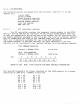
Two checkerboard test patterns ($55 and tAA) are used, first for b~te path immediate data and next for lonSword path immediate data, usin~ reSister dO. Once dO has been verified for immediate addressinS, it is reloaded with the first checkerboard pattern, $55555555. This pattern is then cascaded throu~h all eiSht data re~isters (dO-d7) and all seven address reSisters (aO-a6). The routine is then repeated with dO initialised to the second checker-board pattern, $AAAAAAAA.
PROGRAM MEMORY 7.0.5 A cursory memory te$t is performed, usin~ 32-bit lonsword instructions. The test is in three basic sections: I. 2. 3. Clear proSram memor~ (wri~e all zeroes). This performs an initial check on continuity of memor~ addressins. Restart at the be~innins of memory. Read the current lonSword for all zeroes, write all ones, read for all ones and pro~ress. to the next lon~word until end of memor~.
7.0.8 TABLET PORT Internal loop-back mode is set on the Tablet USART, and the same scheme used to test the CRTC Cursor Resister is implemented here on the data holdins re~ister. The internal loop-back scheme reGuires that the mode re~isters be set UP for normal operations, in order to test the USART as it would normall~ be used.
7.0.10 FIBRE OPTICS ELECTRICAL LOOP-BACK The Fibre Control Register is set for Electrical LoopBack Mode, and two checkerboard patterns ($5555 and SAAAA) are then written to the Host Control and Status Re~ister individually. After writing each pattern, NXM is checked for error status on the packet. If NXM is oka~, then the pattern is read back from the loop-back address. If the packet returns bad information, the data will be either all ones or all zeroes.
7.0.14 KEYBOARD SELF-TEST A reauest for the keYboard's hardware ID times out after If the ID is received, we then call the keyboard's self-test. It is necessary to call the Self-Test a~ain at this point, as the results the previous Self-Test could not be interpreted b~ the uninitialised 68000. The results of the current test are reported to the Keyboard LED's, and to the 68000 via the followin~ four-b~te messa~e: 1 second.
7.1 IDLE LOOP After successful completion of the Powerup code, the 68000 continuouslY loops on a modified version of the same code until the user either lo~s in or enters Maintenance Mode. If Idle Loop fails a test, it does not do an~ more testins until the next pass. All errors are lo~~ed to the host, but onl~ the first error detected is reported to the Mother Board and Keyboard LED's. The followinS tests are executed durin~ Idle Self-Test: 1. 2. 3. 4. 5. 6. 7.
7.2 COMMAND LOOP The host this point. 1. 2. 3. 4. The ma~ followin~ reauest the VS100 to perform WGA commands at commands are defined at microcode level: Reset (~o to Idle Loop via Powerup diasnostics) Send_Command_Packet (includes Move_Object and Report_Status Commands) Start_Displa~_Firmware (transfers control to the displa~ firmware) Init (initialise CSR's and ~o to command loop) Init initialises the Control/Status 1• 2. 3. 4. 5. 7. 6. 8.
7.3 MAINTENANCE MODE Several tests are available to test the input/outPut devices, as well as a special test for the fibre link. All tests in Maintenance Mode reQuire a human interface.
HOUSE FUNCTIONALITY TEST Upon enterin~ this mode, the ?rinted to the screen: ***** Ke~pad o 1 2 VS100 Maintenance Mode -- t~?e function followin~ ke~ messa~e is f4 to exit Options: Return to Main Menu Mouse Button Test Mouse Cursor Test There are basicall~ two aspects of the mouse that need to be tested; directional/ma~nitudinal accurac~ of the cursor, and communication of mouse button events.
MONITOR TEST Upon enterin~ this test, the fol10win~ menu is printed to the screen: ***** VS100 Maintenance Mode -- t~pe function key f4 to exit Keypad Options: o 1 2 3 For Return to Main Menu Universal Alisnment Pattern Stairstep of Halftones TOSSle Screen Contents an~ pattern, the screen is preserved until ·0· is hit to exit. 7.3.3.
be tossled back to what it was b~ selectin~ this command a~ain. TABLET FUNCTIONALITY TEST Upon enterin~ this mode, the printed to the screen: ***** followin~ messaSe i~ VS100 Maintenance Mode -- type function key f4 to exit Keypad Options: o 1 2 R~turn to Main Menu Tablet Button Test Tablet Puck Test Similar to the House Test, except that the Tablet has 5 buttons numbered 0-4. For future adaptabilit~ to 16-button pucks, a decimal conversion routine is used to report the button number.
EXCEPTIONS & INTERRUPTS All two-hundred fift~-six 68000 interrupts and exceptions are suPPorted b~ the microcode, whether or not they can be expected to occur. The 68000 provides two kinds of interrupts; Auto-Vectored and Device-Vectored. The VS100 utilises the Auto-Vector system. All unimplemented interrupts and exceptions result in the ~eneration of an error code/messase.
AUTO-VECTOR INTERRUPTS Seven level$ of interrupts are available on the 68000, in increasins level of priorit~. The hiShest level of interrupt is nonmaskable.
7.5 ERROR REPORTING All dia~nostics at all levels of microcode attempt to report errors in each of three wa~s: i. 2. 3. Error code to Mother Board LED's code to LK201 Ke~board LED's Error code to Host's Interrupt Reason E~ror Re~ister (CSR il) The error code is a n~bble (4 bits) code identifyin~ the test that failed. The code is the same for all three error code output forms. POWERUP: ~reen led off, test. in LEDS. Code set in advance of test.
LED Number 2 3 1 o Dia~nostic Reason ---------~~---~ ---------~--------~-~---------------~-----------~------- ---1---1--o I 0 I 1 0 -------------------------------------------------------ROM Checksum error ---1---1--o I 0 1 1 1 o I 0 I 0 ---1---1--- o I 1 I 0 ---1---1--o 1 1 I 0 1 0 1 68000 CPU error -------------------------------------------------------Pro~ram RAM error -------------------------------------------------------CRTC Re~ister error -----------------------------------
7.6 MANUFACTURING MODE Manufacturin~ Mode is entered upon powerup when a Jumper is in place next to the Mother Board LED's. In this mode, loop-back connectors are used at the ke~board and tablet ports for special tests that are available ONLY when the Jumper is in place and are executed in place of the normal I/O self-tests. At the end of the Powerup SelfTest, the microcode Jumps back to a location in ROM (to be determined) and executes the entire self-test. This c~cle continues indefinitelw.
7.
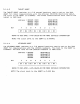
4AOOOO Ixxxxxxxxxxxxxxxxi Ixxxxxxxxxxxxxxxxl 480010 1----------------1 HOST_CSRS I 480000 ---------- ______ 1 8 words xxxxxxxxxxxxxxxxi 260002 1 word 260000 xxxxxxxxxxxxxxxx xxxxxxxxxxxxxxxx 240200 BBA_SCRATCHPAII 256 words 240000 xxxxxxxxxxxxxxxx xxxxxxxxxxxxxxxx 184000 8K words 180000 FRAME_BUFFER 256K words 100000 xxxxxxxxxxxxxxxx xxxxxxxxxxxxxxxx OE0002 RETRY_INFINITE 1 word OEOOOO xxxxxxxxxxxxxxxx OC0002 RETRY_FINITE 1 word OCOOOO xxxxxxxxxxxxxxxx xxxxxxxxxxxxxxxx OAOOOO 641<
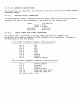
7.8 VS100 STATUS REGISTER Here is a bit • 7 I 1 I I I I t ma~ of the VS100 read-onl~ status reSister: 6 5 4 3 2 1 0 I 1 I ,----- ManlJfacturing Mode (0 = ~es, 1 '--_ ..... BBA Present (0 = '::f.es, 1 = no) I I I \ _ .... --no, 1 ~es) NXM (0 I I I t I \_---- RetrY_Overflow (0 = no, 1 = ~es) = 1 = no) = ..... __ ... Link_Available (0 = no, 1 = ~es) ' .. __ .......
7.8.1 HOUSE CURSOR The mouse cursor re~ister contains two ei~ht-bit counters which kee? track of the mouse's horizontal and vertical moverraer,t: bit + 15 14 13 12 11 10 9 8 7 6 5 4 3 2 1 0 1~71~61~51~41~31~21~11~Olx7Ix6ix5Ix4Ix3Ix2IxllxOf \ __ 1 __ 1 __ 1 __ 1 __ 1 __ 1 __ 1 __ 1 __ 1 __ 1 __ 1 __ 1 __ 1 __ 1 __ 1 __ 1 MOTHER BOARD LED's There are five LED's on the Mother Board; four red LED's and one ~reen LED.
FIBRE CONTROL The fibre control re~ister uses three bits. These are and are used by the hardware. XMIT ON causes the hardware to li~ht the LED at the Mother Board end of the fibre link. The other two signals are dia~nostic signals.
8.0 SOFTWARE 1. OVERVIEW W6A/SDA DESCRIPTION 3. OPERATION 4+ DEVICE DRIVER 2+ The device driver for the VAXSTATION 100 display will permit a callins prosram to send command and arSument lists to the VS100 DISPLAY PROCESSOR. In addition to this basic function, the driver can be instructed to start and stop the displa~ processor,load the ~rocessor microcode from VAX memor~ or disk, and load character fonts.
9.0 PERFORMANCE 1. HARDWARE LIMITS A. memor~ access cycle time B. screen memory access time c. unibus memor~ access time = 400ns. = 800ns. = 1. fiber optiC' 2. worst case unibus access time 3. vax memory cycle time 2. SOFTWARE OVERHEAD T.B.D.
10.0 MAINTAINABILITY RELIABILITY A. SYSTEM M.B.T.F. The s~stem goal is 4000hrs MTTR 2.0 Mrs or less MTTI 4.0 Mrs or less B. SUB-ASSEMBLY M.B.T.F. Calaulated MTBF UNIT MOTHERBOARD U.B.W. F.O.T/R B.B.A H7865 MONITOR LK201 ALL VALUES ARE CALCULATED USEING MIL SPEC STANDARD hrs X 1000 15.1 91.9 278.0 92.53 23.9 15.5 66.8 ( less usea~e than the PC350) 217 @ G.B. CABLES 2000.0 MOUSE 35.0 TILT/SWIVEL n/a FIBER CABLE 87.71 (300m,at min bend rad.) Min bend radius = 3.0cm for whole cable Min bend radius 2.
12.
13.0 REFERENCE MATERIAL DEC. STD. 158 UNIBUS SPECIFICATION A-PS-17-00333-0-0 CABLE,FIBER OPTIC,TWO CHANNEL,UNTERMINATED A-PS-17-00343-0-0 CABLE,FIBER OPTIC, TWO CHANNEL,TERMINATED A-SP-H7865-0-0 POWER SUPPLY, H7865,MULTIPLE OUTPUT,5V,+12V,-12V A-PS-30-20240-0-0 MONITOR,ALPHA/GRAPHIC VIDEO, 19 INCH, MONOCHROME A-PS-30-20037-0-0 TABLET, DIGITIZING A-PS-30-20038-0-1 MOUSE"HAND HELD A-SP-LK201-A-2 LK201 KEYBOARD DESIGN SPECIFICATION WORKSTATION GRAHPIC ARCHITECTURE Driver spec --- latest cop~ V1.