
Technical data

System Dump Analyzer
SHOW PORTS
• BUS data structure for each of the local LAN adapters
• Some of the data structures used by both PEDRIVER and the LAN drivers
The following symbols are defined automatically:
Symbol Explanation or Example
VC_nodename VC_NODE1, address of the local node’s virtual
circuit to node NODE1
CH_nodename The preferred channel for the virtual circuit; for
example, CH_NODE1, address of the local node’s
preferred channel to node NODE1
BUS_busname BUS_ETA, address of the local node’s BUS structure
associated with LAN adapter ETA0
PE_PDT Address of PEDRIVER’s port descriptor table
MGMT_VCRP_busname MGMT_VCRP_ETA, address of the management
VCRP for BUS ETA
HELLO_VCRP_busname HELLO_VCRP_ETA, address of the HELLO
message VCRP for BUS ETA
VCIB_busname VCIB_ETA, address of the VCIB for BUS ETA
UCB_LAVC_busname UCB_LAVC_ETA, address of the LAN device’s UCB
used for the local area VAXcluster protocol
UCB0_LAVC_busname UCB0_LAVC_ETA, address of the LAN device’s
template UCB
LDC_LAVC_busname LDC_LAVC_ETA, address of the LDC structure
associated with LAN device ETA
LSB_LAVC_busname LSB_LAVC_ETA, address of the LSB structure
associated with LAN device ETA
These symbols equate to system addresses for the corresponding data structures.
You can use these symbols, or an address, after the equal sign in SDA commands.
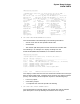
The SHOW PORTS command produces several displays. The initial display, the
PDT summary page, lists the PDT address, port type, device name, and driver
name for each PDT. Subsequent displays provide information taken from each
PDT listed on the summary page.
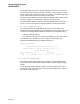
You can use the /ADDRESS qualifier of the SHOW PORTS command to produce
more detailed information about a specific port. The first display of the SHOW
PORTS/ADDRESS command duplicates the last display of the SHOW PORTS
command, listing information stored in the port’s PDT. Subsequent displays list
information about the port blocks and virtual circuits associated with the port.
SDA–143