
User`s guide


The XMI
2.8 XMI REGISTERS
This section describes the registers required for various types of
nodes.
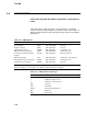
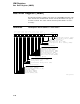
Each XMI node is required to have a set of registers in a specified
location within the node’s nodespace, as shown in Table 2–16. Table 2–17
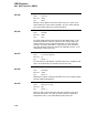
defines the abbreviations used to describe the type of bits in the register
descriptions.
Table 2–16 XMI Registers
Register Mnemonic Address Node Requirements
Device Register XDEV
1
BB
2
+ 0000 0000 All nodes
Bus Error Register XBER BB + 0000 0004 All nodes
Failing Address Register XFADR BB + 0000 0008 Commanders only
XMI General Purpose Register XGPR BB + 0000 000C Commanders only
Node-Specific Control and Status
Register
NSCSR BB + 0000 001C All nodes (optional)
XMI Control Register XCR BB + 0000 0024 Commanders only (optional)
Failing Address Extension Register XFAER BB + 0000 002C Commanders only
Bus Error Extension Register XBEER BB + 0000 0034 All nodes
1
X in the mnemonic indicates that this is an XMI register.
2
BB = base address of a node, which is the address of the first location in nodespace.
Table 2–17 Abbreviations for Bit Type
Abbreviation Definition
0 Initialized to logic level zero
1 Initialized to logic level one
X Initialized to either logic state
RO Read only
R/W Read/write
R/W1C Read/cleared by writing a 1
WO Write only
MBZ Must be zero
2–56