
User`s guide


The XMI
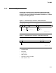
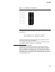
Figure 2–10 XMI Address Interpretation
A<i>, i= 4 3 2 1 0
Read longword
Read quadword
Read octaword
Read hexword
Write longword
Write quadword
Write octaword
Write hexword
s
s = significant
x = don’t care
msb−p173−89
ssss
ssxxx
ssxxx
ssxxx
sssss
ssxxx
sxxxx
xxxxx
The relationship between the high and low words, the state of A<1>, and
the data bits is:
A<1> = XMI D<1> = 1 high word D<31:16>
A<1> = XMI D<1> = 0 low word D<15:0>
The data returned on the opposite word of the one specified will have
correct parity, but its data is unspecified.
For a longword-oriented device, A<1> is ignored as an address bit and a
full longword of data is returned for a read operation.
2.4.2.5 Interrupt Priority Level Field
XMI D<19:16> carries the interrupt priority level (IPL) during the
command cycle of an interrupt transaction (INTR, IDENT, or IVINTR).
Each bit corresponds to a priority level, with XMI D<19> the highest
priority of the four, corresponding to IPL 17 on VAX systems, while bits
XMI D<18>, XMI D<17>, and XMI D<16> correspond to IPL 16, 15, and
14, respectively, on VAX systems. One or more of these bits can be set in
any given command cycle.
2–27