
User`s guide


The XMI
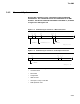
2.4 XMI Cycles
The purpose of an XMI cycle is determined by four signal lines on
the XMI backplane, XMI F<3:0> L.
2.4.1 Function Codes
The XMI uses four lines to encode the function being performed on the
bus. Table 2–9 lists the function codes.
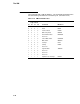
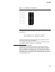
Table 2–9 XMI Function Codes
XMI F<3:0> L
Logic Levels
3 2 1 0 Function Mnemonic
0 0 0 0 NULL cycle NULL
0 0 0 1 Command cycle CMD
0 0 1 0 Write Data cycle WDAT
0 0 1 1 Reserved (decoded as NULL)
0 1 0 0 Lock Response LOC
0 1 0 1 Read Error Response RER
0 1 1 0 Reserved (decoded as NULL)
0 1 1 1 Reserved (decoded as NULL)
1 0 0 0 Good Read Data 0 GRD0
1 0 0 1 Good Read Data 1 GRD1
1 0 1 0 Good Read Data 2 GRD2
1 0 1 1 Good Read Data 3 GRD3
1 1 0 0 Corrected Read Data 0 CRD0
1 1 0 1 Corrected Read Data 1 CRD1
1 1 1 0 Corrected Read Data 2 CRD2
1 1 1 1 Corrected Read Data 3 CRD3
2–22