
User`s guide


The XMI
2.2.2.2 XMI Nodespace
The VAX 6000 platform XMI nodespace is a collection of 16 512-Kbyte
regions located from E180 0000 to E1FF FFFF (32-bit address) or
from 2180 0000 to 21FF FFFF (30-bit address). Nodes 0 and F are not
implemented. Each XMI node is allocated one of the 512-Kbyte regions
for its control and status registers. The starting address of the 512-Kbyte
region associated with a given node is computed as follows:
E180 0000 + Node ID * 80000 (32-bit address)
2180 0000 + Node ID * 80000 (30-bit address)
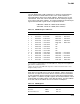
Table 2–5 XMI Nodespace Addresses
Slot Node Nodespace I/O Window Space
1 1 E188 0000 – E18F FFFF
1
E200 0000 – E3FF FFFF
2 2 E190 0000 – E197 FFFF E400 0000 – E5FF FFFF
3 3 E198 0000 – E19F FFFF E600 0000 – E7FF FFFF
4 4 E1A0 0000 – E1A7 FFFF E800 0000 – E9FF FFFF
5 5 E1A8 0000 – E1AF FFFF EA00 0000 – EBFF FFFF
6 6 E1B0 0000 – E1B7 FFFF N/A
2
7 7 E1B8 0000 – E1BF FFFF N/A
8 8 E1C0 0000 – E1C7 FFFF N/A
9 9 E1C8 0000 – E1CF FFFF N/A
10 A E1D0 0000 – E1D7 FFFF F400 0000 – F5FF FFFF
11 B E1D8 0000 – E1DF FFFF F600 0000 – F7FF FFFF
12 C E1E0 0000 – E1E7 FFFF F800 0000 – F9FF FFFF
13 D E1E8 0000 – E1EF FFFF FA00 0000 – FBFF FFFF
14 E E1F0 0000 – E1F7 FFFF FC00 0000 – FDFF FFFF
1
To convert these 32-bit addresses to 30-bit addresses, change the most significant
byte from E to 2 and from F to 3.
2
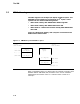
Slots in the center of the XMI card cage have no I/O connectors because of the
daughter card’s presence.
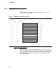
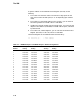
Each device on the XMI has its own set of registers. Table 2–6 lists only
those that are required of all XMI devices. Devices that are commanders
or that implement optional registers may be required to implement other
XMI registers. To address any XMI register, take the base address of each
node (the BB) and add the offset of the desired register. The base address
of an XMI node is the address of its first location in nodespace.
Table 2–6 XMI Registers
Register Mnemonic Address
Device XDEV BB + 00
Bus Error XBER BB + 04
Bus Error Extension XBEER BB + 34
2–15