
User`s guide


The VAX 6000 Platform Overview
1.10 Cooling System
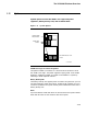
The cooling system consists of two blowers, an airflow sensor, a
temperature sensor, and an airflow path through the card cages
and up to the power regulators.
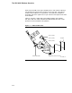
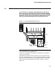
Figure 1–10 Airflow Pattern
REAR
EXTERNAL
FRONT VIEW
INTERNAL
SIDE VIEW
FRONT
POWER
REGULATORS
CARD CAGES
BLOWERS
msb-0008-89
The cooling system is designed to keep system components at an optimal
operating temperature. The front and back of the cabinet should be free of
obstructions to maximize air intake.
The blowers, located in the lower half of the cabinet, draw air in through
the doors and push air up through the card cages. The air is directed
through a duct to cool the console load device if there are no VAXBI card
cages in the system. The airflow continues through the top of the card
cages, through the power regulators, and out the top of the front and rear
doors. A fan cools the power and logic box.
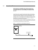
The system has safety detectors for the cooling system: an airflow sensor
and a thermostat are installed above the power regulators in the top of the
cabinet. Extreme conditions activate these detectors. Under extreme
temperatures, the thermostat shuts off all output power (including
power at the two unswitched outlets) at the AC power controller. In
this condition the battery backup unit is disabled and will not provide
power. If the airflow to the system is seriously blocked for an extended
period of time, the airflow sensor shuts off the power supply.
1–14