
User`s guide


DWMBB Adapter
3.14.3.2 Forcing Bad Parity on the BCI
Forcing bad parity on the BCI, by using Force BCI Bad Parity
(BDCR1<2>), allows diagnostics to verify the BCI data path. When Force
BCI Bad Parity is set, bad parity is forced on the BCI by the DWMBB/B
module gate array. The BIIC logs the error and, if BIIC loopback mode is
disabled, transmits the bad parity to the VAXBI, where it results in a bus
error. This allows diagnostics to verify the BIIC parity checker and the
BCI data path, but does not allow isolation of a parity problem to either
the DWMBB/B module gate array or the BIIC because the DWMBB/B
module gate array does not check parity on the BCI.
3.14.4 ECC and the ECC RAMs Testing
Testing the ECC error detection and correction of the PMR data path uses
the 16 diagnostic bits listed in Table 3–21.
Substitute ECC, Force ECC Error, and Latch Check Bits allow diagnostics
to write test patterns to the ECC RAMs and then verify that the RAMs
contain the correct pattern. The bits also allow diagnostics to write
good ECC with bad data to the RAMs, verifying the ECC detection and
correction logic.
Substitute ECC, Force ECC Error, Latch Check Bits, and ECC Disable
allow diagnostics to verify the RAM even if the ECC logic has failed.
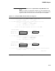
Table 3–21 ECC Diagnostic Bits
Name Location Description
Diagnostic ECC<11:0> ADG1<25:14> Used as a diagnostic ECC field.
Substitute ECC ADG1<13> Enables Diagnostic ECC<11:0> to be written out to the PMRs
instead of the normally generated check bits. This allows
diagnostic software to write any pattern into the ECC RAMs,
thereby forcing correctable and uncorrectable errors to occur,
verifying the ECC logic.
Force ECC Error ADG1<11> Forces an ECC error on any transaction that reads good data.
If the data read out of the PMR is good and Force ECC Error is
set, the "ECC Correctable Error" signal is asserted.
Latch Check Bits ADG1<12> Forces the ECC bits to be logged in ACSR instead of the
syndrome bits when an ECC error is detected, giving diagnostics
a window into the ECC RAMs.
ECC Disable ADG1<0> Disables the detection and correction functions of the ECC logic.
With this bit set, no Interrupts or Implied Vector Interrupts due to
ECC errors can be generated. Force ECC Error overrides ECC
Disable. If both bits are set, errors are forced on accesses to
the PMRs.
3–146