
User`s guide


DWMBB Adapter
3.14.2.1 Executing DMA Writes and Reads in Loopback Mode
Diagnostic software tests all the DMA data and C/A buffers in the
transaction register file by using DMA loopback mode or DWMBB/A
module loopback mode to send DMA write data to any one of the longword-
length locations in either of the DMA data buffers. The data is then
written to XMI memory, where it is checked for accuracy. DMA read
commands are used to verify the data that was sent to XMI memory.
The following are used to test the DMA buffers in the transaction register
file:
• DMA loopback write/read commands
• Force DMA-A Buffer Busy and Force DMA-B Buffer Busy (ADG1<5:4>)
• DWMBB/A Flip Failing Address Bit<1> (ADG1<9>) or DWMBB/B Flip
Failing Address Bit<1> (BDCR1<6>)
• I/O C/A Address Bit<2> to convert the original I/O command to a DMA
loopback command
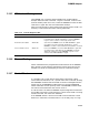
Table 3–20 lists the diagnostic bits required to test the transaction register
file in various loopback modes.
Table 3–20 Diagnostic Bits That Test the Transaction Register File in Loopbacks
DWMBB/A
Loopback Mode
DMA Loopback Mode
Transmit Buffer Tested
Diagnostic Bits Used DMA-A DMA-B DMA-A DMA-B
Force Octaword Transfers 1 1 1 1
DWMBB/A Loopback Enable 1 1 0 0
DWMBB/A Flip Address Bit<29> 1 1 X X
DWMBB/A Flip Failing Address Bit<1> 1/0 1/0 X X
Force DMA-A Buffer Busy 0 1 0 1
Force DMA-B Buffer Busy 1 0 1 0
DWMBB/B Flip Address Bit<29> X X 1 0
DWMBB/B Flip Failing Address Bit<1> X X 1/0 1/0
The DMA-A and DMA-B transaction buffers can be tested in either
DWMBB/A module loopback mode or DMA loopback mode using loopback
DMA writes and reads. The DMA loopback mode cannot be used while
DWMBB/A module loopback mode is enabled because the DWMBB/A
module gate array does not pass any I/O transactions to the DWMBB/B
module while the DWMBB/A module is in loopback mode.
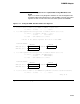
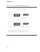
An example of a loopback DMA write followed by a loopback DMA read
follows:
1 Set Force Octaword Transfers to force octaword DMA transactions on
the XMI
3–141