
User`s guide


DWMBB Adapter
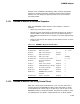
D<12:8> are all zeros to indicate that one of the BIIC internal registers
is selected. D<7:0> specify the register, the same as during a VAXBI
transaction.
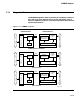
3.14.1.3 DMA Loopback
During DMA loopback mode, the main data path includes the DWMBB/A
module, the IBUS, the DWMBB/B module, and the VAXBI. The mode is
entered by setting DWMBB/A Flip Address Bit<29> (BDCR1<4>).
In this mode, I/O C/A cycles from the XMI, directed to the DWMBB
I/O window space, have XMI Address Bit<29> and the BCI parity bit
inverted by the master sequencer, so that the transaction looks like a
DMA transaction originating from the VAXBI. The DWMBB is the selected
slave for the transaction and processes the transaction like any other
VAXBI-initiated DMA transaction.
The DWMBB/A module clears I/O command/address bits <28:25> when
transferring an I/O C/A cycle to the DWMBB/B module as the DWMBB
has only 32 Mbytes of addressable I/O adapter space. Therefore, these bits
are zero during DMA loopback mode.
Normal DMA transactions should not be done in DMA loopback mode as
the results are undefined.
3–136