
User`s guide


DWMBB Adapter
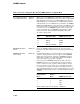
3.14.1 Internal Loopback Modes
Loopback modes help isolate a fault to an area of logic by enabling
software to test segments of the main data path. The three types of
DWMBB loopbacks are:
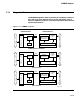
• DWMBB/A module loopback — Data path to the DWMBB/A module
• BIIC loopback — Data path includes DWMBB/A module and
DWMBB/B module
• DMA loopback — Data path includes DWMBB/A module, DWMBB/B
module, and the VAXBI
The three DWMBB loopbacks are illustrated in Figure 3–14.
All loopback transactions originate as longword I/O transactions on the
XMI. DWMBB/A module and DMA loopbacks allow diagnostic programs
executing on the XMI to have I/O transactions to the VAXBI converted
into DMA transactions that access XMI memory. BIIC loopback allows
transactions to be made to BIIC registers without use of the VAXBI data
lines.
When a loopback mode is enabled and an XMI I/O read transaction
directed to a VAXBI node is accepted by the DWMBB, the DWMBB
converts the I/O read into a DMA read. The I/O command is converted
to a quadword (or octaword, if the proper diagnostic bit is enabled) DMA
read. The XMI returns the full quadword (or octaword) of data to the
DWMBB.
During loopback modes, the DWMBB/A module gate array uses a longword
of that returned DMA read data as return read data for the original XMI
I/O read command. The returned longword depends on the value of the
original I/O address and the setting of diagnostic bits, as detailed in
Section 3.14.2.
When either DWMBB/A module or DMA loopback mode is enabled and
an XMI I/O write transaction directed to a VAXBI node is accepted by the
DWMBB, the DWMBB converts the I/O write to a quadword (or octaword,
if the proper diagnostic bit is enabled) DMA write. The longword of write
data from the original I/O write C/A and the contents of the DMA data
buffers of the transmit registers form the quadword (or octaword) of data
that is issued on the XMI.
3.14.1.1 DWMBB/A Module Loopback
During DWMBB/A module loopback, the main data path does not use
the IBUS or the DWMBB/B module. Diagnostic software can then isolate
a failure to the DWMBB/A module and test DWMBB/A module error
conditions faster than if the DWMBB/B module was tested simultaneously.
DWMBB/A module loopback mode requires setting both DWMBB/A
Loopback Enable (ADG1<7>) and DWMBB/A Flip Address Bit<29>
(ADG1<8>). DWMBB/A Flip Address Bit<29> causes address bit<29> and
the parity on the C/A cycle to be flipped so that the address is pointing to
memory space instead of I/O space.
3–134