
User`s guide


DWMBB Adapter
Software, once in DWMBA compatibility mode, loads the appropriate
registers for enabling interrupts and DMA transfers to/from memory.
Software can also change the operating mode to one of the address
translation modes.
3.13.1 DWMBB/A Module Initialization Sequence
When the DWMBB/A module detects a reset condition, it does the
following:
• Aborts any transaction in progress.
• Sequences a total initialization of the PMRs by writing all 32 bits of
the 64 K PMRs to zero and NO ACKs any I/O address targeting a
PMR while the initialization is in progress. This takes approximately
8.4 ms.
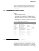
• Resets all control logic and registers to their default values, as shown
in Table 3–17.
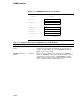
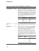
Table 3–17 DWMBB/A Register Default Values
Location Name Status Value
XBER<2> XMI Timeout Enabled 0
AUTLR<23:20> XMI Timeout Limit – 14 – 15 ms
ACSR<8> XMI Lockout Response Enabled 1
ACSR<7> XMI Lockout Assert Enabled 1
AUTLR<31:28> XMI Lockout Limit – 4 IREADs
AUTLR<27:24> Lockout Deassertion Timer – 2 – 3 ms
ACSR<4> Responder Arbitration
Request
Disabled 0
ACSR<1> Return Vector Disable Disabled 0
ACSR<5> VAXBI Window Space Enable Disabled 0
ACSR<9> Short Timeout Enable Disabled 0
ADG1<31:0> Diagnostic Options Disabled 0
AIMR<31:0> DWMBB/A-Detected Error
Interrupts
Disabled 0
AUTLR<19:18> Address Translation Disabled 0
3.13.2 DWMBB/A Module Gate Array Control Reset
When the Control Reset (ACSR<30>) bit is set, a partial node reset is
initiated, allowing the DWMBB/A module’s CSRs and PMRs to remain
unchanged while all control logic in the gate array and all logic on the
DWMBB/B module, including the VAXBI, initialize to the power-up state.
Any pending XMI I/O requests, VAXBI DMA writes, or INTR requests
3–131