
User`s guide


DWMBB/B Module Registers
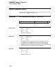
Diagnostic Control Register 1 (BDCR1)
bit<5>
Name: Reserved
Mnemonic: None
Type: RO, 0
Reserved; must be zero.
bit<4>
Name: DWMBB/B Flip Address Bit<29>
Mnemonic: B Flip A29
Type: R/W, 0
Setting DWMBB/B Flip Address Bit<29> inverts the state of
Address<29> and BCI parity after the I/O C/A has been fetched
and decoded by the DWMBB/B module. The new address, which
now points to XMI memory space, is issued to the VAXBI. The
DWMBB processes this transaction like any other VAXBI-initiated
DMA longword transaction, allowing diagnostic programs executing
on the XMI to issue an I/O transaction to the DWMBB, which then
converts it into a DMA transaction.
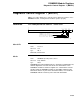
bit<3>
Name: Force BIIC Loopback Mode
Mnemonic: None
Type: R/W, 0
All requests to the master port of the BIIC become loopback requests
whenever BIIC loopback mode is set. Thus the master sequencer can
make loopback requests to access BIIC registers. The loopback mode
prevents the BIIC from initiating VAXBI cycles to access the BIIC
registers. When the BIIC is in BIIC loopback mode, it ignores the node
ID portion of the address presented to it.
bit<2>
Name: Force BCI Bad Parity
Mnemonic: None
Type: R/W, 0
When Force BCI Bad Parity is set, bad parity is forced onto the VAXBI
during CPU C/A, CPU data cycles, and DMA read data cycles.
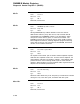
bits<1:0>
Name: Reserved
Mnemonic: None
Type: RO, 0
Reserved; must be zero.
3–110