
User`s guide


DWMBB/B Module Registers
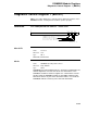
Interrupt Destination Register (BIDR)
Interrupt Destination Register (BIDR)
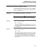
The Interrupt Destination Register is used in two ways: First the DWMBB
uses the lower sixteen bits to identify which node is to receive an error/status
interrupt. Second, diagnostics use the entire register to verify the data path
integrity of the DWMBB/B module.
ADDRESS
XMI nodespace base address + 0000 0048
3
1
1
6
1
50
Diagnostic Read/Write Interrupt Destination
msb−p115−89
bits<31:0>
Name: Diagnostic Read/Write
Mnemonic: None
Type: R/W, undefined
The Diagnostic Read/Write field is used by diagnostics to verify much
of the data path integrity of the DWMBB/B module gate array. The
entire register is R/W so the diagnostics can use the full 32-bit register
for testing purposes.
bits<15:0>
Name: Interrupt Destination
Mnemonic: None
Type: R/W, 0
The Interrupt Destination field determines the nodes on the XMI that
are targeted by the DWMBB when it issues an interrupt transaction.
Each bit in the 16-bit field corresponds to one of the 16 XMI nodes
(only 14 nodes are used in VAX 6000 systems). When a bit is set to
one, the selected node is the targeted node that the DWMBB will
interrupt. Multiple bits can be set to interrupt as many XMI nodes as
the user desires.
3–105