
User`s guide


DWMBB/A Module Registers
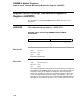
Diagnostic 1 Register (ADG1)
bit<5>
Name: Force DMA-A Buffer Busy
Mnemonic: FORCE DMA-A BUSY
Type: R/W, 0
When set, the Force DMA-A Buffer Busy bit forces the DMA buffer
control logic to place the DMA-A buffer into the busy state, forcing all
DMA traffic through the DMA-B buffer.
CAUTION: If both ADG1<5> and ADG1<4> are set, all legal DMA
transactions stall.
bit<4>
Name: Force DMA-B Buffer Busy
Mnemonic: FORCE DMA-B BUSY
Type: R/W, 0
When set, the Force DMA-B Buffer Busy bit forces the DMA buffer
control logic to place the DMA-B buffer into the BUSY state, forcing
all DMA traffic through the DMA-A buffer.
CAUTION: If both ADG1<5> and ADG1<4> are set, all legal DMA
transactions stall.
bit<3>
Name: Force Bad IBUS Receive Parity
Mnemonic: FOR BAD IBUS RCV PAR
Type: R/W, 0
Force Bad IBUS Receive Parity, when set, causes the received IBUS
parity bit to be a one, regardless of the data. Diagnostics use this bit
along with specific data patterns to force IBUS parity errors on the
DWMBB/A module when the DWMBB/B module loads the IBUS data
into the DWMBB/A module gate array.
bit<2>
Name: Force Bad IBUS Transmit Parity
Mnemonic: FOR BAD IBUS XMIT PAR
Type: R/W, 0
Force Bad IBUS Transmit Parity, when set, causes the parity bit sent
to the DWMBB/B module for IBUS parity to be a one, regardless of the
data that resides in the buffer. Diagnostic routines use this bit and
specific data patterns to force IBUS parity errors when the DWMBB/B
module fetches DMA read data or I/O transactions from the DWMBB/A
module.
3–79