
User`s guide

DWMBB Adapter
Both modules of the DWMBB detect conditions that require an interrupt
to be issued, but only the DWMBB/B module issues interrupts. If the
DWMBB/A module detects an interrupt condition, it flags the DWMBB/B
module using an IBUS signal. The DWMBB/B module then issues the
interrupt when it detects this flag.
The XMI commander eventually responds to the INTR command by
issuing an IDENT command to the DWMBB at the same IPL. When the
DWMBB detects the IDENT command, it responds by issuing an interrupt
vector back to the commander that issued the IDENT. If multiple nodes
are targeted in the IDENT command’s destination field, the DWMBB does
not accept the IDENT.
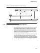
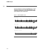
Figure 3–7 shows the Interrupt, IDENT, and Return Vector formats on
XMI D<63:0>.
The interrupts that the DWMBB generates are:
• DWMBB-detected error interrupts. These are caused by an error in
this node. The interrupt vector returned to the XMI is the contents of
BVR<15:2>.
• VAXBI node interrupts. These are generated by a VAXBI node or
by the DWMBB/B module’s BIIC. The VAXBI vector<13:9> is always
zero. The DWMBB/B module’s BVOR<15:9> is inserted into VAXBI
vector<15:9> before passing it to the XMI.
• VAXBI offsettable bus interrupts. These are caused by a VAXBI
interrupt from some bus other than the VAXBI, such as the UNIBUS.
Vector<13:9> is not zero. The DWMBB passes the interrupt from the
VAXBI to the XMI without modification.
• VAXBI IPINTR interrupts. These are caused by VAXBI interprocessor
interrupts. The vector returned to the XMI is the contents of the
BIIC’s UINTRCSR.
• Implied vector interrupts (IVINTRs). These are generated by the
DWMBB in response to an error that could result in the corruption
or loss of data. IVINTRs are executed in one XMI cycle and have
no IDENT cycle or vector associated with them. All IVINTRs are
generated by the DWMBB/A module.
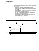
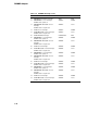
Table 3–4 lists the types of interrupts with the vector source that the
DWMBB generates in response to the various VAXBI interrupts or
DWMBB-detected errors.
3–19