
Installation guide


Unpacking and Assembling Cabinets 2-31
the site, and disable all air circulation equipment. If appro-
priate, quarantine the site and start an environmental disas-
ter recovery process. Avoid touching anything without proper
protective clothing. If electrolyte contacts the skin, WASH IT
OFF IMMEDIATELY and use the appropriate Customer Serv-
ice Process for followup medical treatment. If electrolyte con-
tacts the eyes, FLUSH IMMEDIATELY AND THROUGHLY
WITH WATER FOR 15 MINUTES and follow the recom-
mended Digital Health and Safety Group procedure.
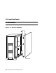
CAUTION: Before starting, make sure that the battery cable connec-
tors in the battery cabinets (see Figure 2-17 for locations)
are all disconnected. Also disconnect all power regulators
in the expander cabinet(s) by backing them out of their
slots approximately 1 to 2 inches. Failure to follow these pre-
cautionary steps may lead to damage of the regulators and/or
fuses. Do not reinstall regulators until battery cables and fuses
have all been installed. Do not defeat the operation of the stop
tabs on the regulators.
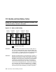
The battery cables are tie-wrapped together in a coil at the bottom of a bat-
tery cabinet. There are six large diameter battery power cables (three orange
and three blue) terminated with metal ring terminals and one group of
smaller diameter battery sense cables terminated with a square 9-pin connec-
tor.
The six large diameter battery power cables are grouped as three pairs of or-
ange (+) and blue (–) connections. Each pair is to be connected to a corre-
sponding power regulator in the expander cabinet. The end of each pair has a
color coded label attached to it as shown in Table 2-2. The label text indicates
to which regulator the pair must be connected (A, B, or C).
Table 2-2 Battery Cable Labeling
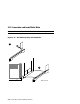
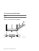
Route the cables from a battery cabinet to the DC distribution box in an ex-
pander cabinet as illustrated in Figure 2-15.
Label Text Label Color
A
Green
B
Blue
C
White