
Installation guide


Powering Up the System 6-7
1. Turn the power on by pushing the circuit breaker handle up.
2. Go to the front of the cabinet and check that the green power regulator
LED(s) are blinking.
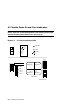
3. Place the control panel keyswitch in the Enable position. The follow-
ing should occur (see Figure 6-3):
a. The yellow Fault indicator on the control panel blinks slowly
(about once per second) indicating power sequencing is taking
place. If the LED blinks rapidly (about 8 times per second), a fail-
ure during the power-up sequence occurred and you should refer to
the Advanced Troubleshooting manual for diagnostic assistance.
b. The blowers turn on.
c. The yellow Fault indicator stays on continuously for a short time
indicating self-test is taking place. Module self-test LEDs light as
described in Section 7.1 and a self-test console display appears on
the console terminal as described in Section 7.2. The console
prompt appears at the end of a successful self-test display.
d. The yellow Fault indicator goes out when self-test passes for all
modules in the system.
Go to the rear and check the CCL LEDs (see Figure 6-3) for system and
expander cabinets.
The cabinet control logic (CCL) module has four LEDs that are visible
through a shield slot when a system or expander cabinet rear door is
opened. These LEDs verify that the enable signals have been sent to the
power regulators for PIUs 1 to 4. The LEDs are numbered one to four,
corresponding to the PIUs. There are no LEDs associated with PIUs 5 and
6 in the top of an expander cabinet.
The LEDs are lit if a PIU is present and power sequencing has been com-
pleted. If a LED is not lit, the PIU is not present, the PIU is not cabled
correctly, or the CCL module has not enabled the PIU.
The CCL module also has a power LED that lights when the circuit
breaker is turned on; the LED indicates that 5 VDC is present on the CCL
module.
For more information:
Basic Troubleshooting
Advanced Troubleshooting