
Installation guide


Powering Up the System 6-5
1. Check that the receptacle provided is correct. This should have been
done during site preparation.
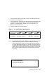
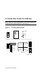
2. Using a voltmeter, measure the voltages between all three phases and
each phase to neutral (see Figure 6-2). Verify that the voltages are
within the range specified in Table 6-1. If the voltages are out of
range, contact an electrician.
3. Plug the power cord into the receptacle.
Table 6-1 AC Input Voltage Specifications
NOTE: In some installations, power regulators must be balanced so the AC
power distribution system will not be overloaded. Balancing
means connecting AC power so that the loads from the regulators
are evenly distributed among the AC phases. This ensures that any
one phase does not draw excessive power. There are three slots for
power regulators, with each slot representing a phase. Power regu-
lators may be moved to different slots to balance the load among
AC phases.
Voltage
Measurement
208V
Nominal
202V
Nominal
380V
Nominal
415V
Nominal
phase–phase
180–220V 180–220V 331–407V 360–443V
phase–neutral
104–128V None 190–235V 208–256V
For more information:
Site Preparation Guide
A
B
C C