DEC 7000 AXP System VAX 7000 Operations Manual Order Number EK–7000B–OP.002 This manual is intended for the system manager or system operator and covers the basic operations of a DEC 7000 AXP system or VAX 7000 system.
First Printing, November 1992 The information in this document is subject to change without notice and should not be construed as a commitment by Digital Equipment Corporation. Digital Equipment Corporation assumes no responsibility for any errors that may appear in this document. The software, if any, described in this document is furnished under a license and may be used or copied only in accordance with the terms of such license.
Contents Preface ..................................................................................................... vii Chapter 1 DEC 7000 AXP System and VAX 7000 System 1.1 1.2 1.3 1.4 1.5 System Characteristics .......................................................... 1-2 System Architecture .............................................................. 1-4 Sample System ....................................................................... 1-6 System Front View ....................................
.2 4.3 4.3.1 4.3.2 4.4 4.4.1 4.4.2 4.5 4.5.1 4.5.2 4.5.3 4.5.4 4.6 4.6.1 4.6.2 4.6.3 4.7 4.7.1 4.7.2 4.7.3 4.7.4 4.7.5 4.7.6 Booting Overview ................................................................... 4-4 Boot Command Syntax .......................................................... 4-6 Console Environment Variables ................................... 4-10 Set Commands for Booting .......................................... 4-12 Booting Concepts ....................................................
Glossary Examples 4-1 4-2 4-3 4-4 4-5 4-6 4-7 4-8 4-9 4-10 C-1 C-2 C-3 C-4 C-5 C-6 C-7 Set Boot Commands ............................................................. 4-12 CD-ROM OpenVMS Alpha AXP Boot ................................ 4-20 CD-ROM OSF/1 Boot .......................................................... 4-22 Sample Local Device Boots .................................................. 4-24 InfoServer OpenVMS VAX Boot ......................................... 4-28 Selecting an Ethernet Service ..
4-4 4-5 4-6 4-7 4-8 4-9 4-10 Boot Procedure ..................................................................... 4-14 Determining the Boot Processor .......................................... 4-16 Local Device Booting ............................................................ 4-18 InfoServer Selection Flowchart ........................................... 4-26 InfoServer Configuration ..................................................... 4-27 Booting from CI and DSSI VMSclusters .........................
Preface Intended Audience This manual is written for the system manager or system operator who has training in systems management and is running a DEC 7000 AXP system or a VAX 7000 system. Document Structure This manual uses a structured documentation design. Topics are organized into small sections for efficient on-line and printed reference. Each topic begins with an abstract. You can quickly gain a comprehensive overview by reading only the abstracts.
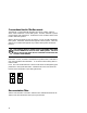
Conventions Used in This Document Terminology. Unless specified otherwise, the use of "system" refers to either a DEC 7000 AXP or VAX 7000 system. The DEC 7000 AXP systems use the Alpha AXP architecture. References in text use DEC 7000 to refer to DEC 7000 AXP systems. When a discussion applies to only one system, an icon is used to highlight that system. Otherwise, the discussion applies to both systems.
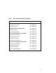
Table 1 DEC 7000/VAX 7000 Documentation Title Order Number Installation Kit EK–7000B–DK Site Preparation Guide EK–7000B–SP Installation Guide EK–700EB–IN Hardware User Information Kit EK–7001B–DK Operations Manual EK–7000B–OP Basic Troubleshooting EK–7000B–TS Service Information Kit—VAX 7000 EK–7002A–DK Platform Service Manual EK–7000A–SV System Service Manual EK–7002A–SV Pocket Service Guide EK–7000A–PG Advanced Troubleshooting EK–7001A–TS Service Information Kit—DEC 7000 EK–7002
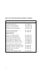
Table 1 DEC 7000/VAX 7000 Documentation (Continued) Title Order Number Reference Manuals Console Reference Manual EK–70C0B–TM KA7AA CPU Technical Manual EK–KA7AA–TM KN7AA CPU Technical Manual EK–KN7AA–TM MS7AA Memory Technical Manual EK–MS7AA–TM I/O System Technical Manual EK–70I0A–TM Platform Technical Manual EK–7000A–TM Upgrade Manuals x KA7AA CPU Installation Guide EK–KA7AA–IN KN7AA CPU Installation Guide EK–KN7AA–IN MS7AA Memory Installation Guide EK–MS7AA–IN KZMSA Adapter Installa
Table 2 Related Documents Title Order Number General Site Preparation Site Environmental Preparation Guide EK–CSEPG–MA System I/O Options BA350 DECstor/me Modular Storage Shelf Subsystem Configuration Guide EK–BA350–CG BA350 DECstor/me Modular Storage Shelf Subsystem User’s Guide EK–BA350–UG BA350-LA DECstor/me Modular Storage Shelf User’s Guide EK–350LA–UG CIXCD Interface User Guide EK–CIXCD–UG DEC FDDIcontroller 400 Installation/Problem Solving EK–DEMFA–IP DEC LANcontroller 400 Installation
Table 2 Related Documents (Continued) Title Order Number Operating System Manuals Alpha Architecture Reference Manual EY–L520E–DP DEC OSF/1 Guide to System Administration AA–PJU7A–TE DECnet for OpenVMS Network Management Utilities AA–PQYAA–TK Guide to Installing DEC OSF/1 AA–PS2DA–TE OpenVMS Alpha Version 1.
Chapter 1 DEC 7000 AXP System and VAX 7000 System The DEC 7000 AXP system and VAX 7000 systems are designed for growth offering configuration flexibility, an outstanding I/O subsystem, and expansion capability in a single or multicabinet environment. The DEC 7000 system or VAX 7000 system can support many users in a timesharing environment.
1.1 System Characteristics DEC 7000 and VAX 7000 systems share characteristics as shown in the tables. Figure 1-1 shows a system footprint. Sample System Footprint System Cabinet Expander Cabinet 170 cm (67 in) 170 cm (67 in) Expander Cabinet 80 cm (31.5 in) 170 cm (67 in) Figure 1-1 80 cm (31.5 in) 80 cm (31.5 in) Rear Clearance 100 cm (39 in) Expander Cabinet System Cabinet Expander Cabinet Width 240 cm (94.5 in) 87.5 cm (34.5 in) Depth 337.5 cm (132.
The values in Table 1-1 apply to the system cabinet only. The values are configuration dependent. Additional options will increase electrical requirements so that an additional power regulator may be needed. Table 1-1 Electrical Characteristics Electrical Specification 3-phase AC input voltage 202 V RMS 120/208 V RMS 380–415 V RMS Nominal frequency 50–60 Hz AC current, nominal, (per phase) 24 A (202 V) 24 A (120/208 V) 12.
1.2 System Architecture The high-speed LSB bus is used to interconnect processors, memory modules, and the IOP module.
The LSB bus is a synchronous 128-bit system bus that interconnects the processors, memory modules, and the I/O port (IOP) module. The IOP module connects the LSB bus to I/O buses through separate I/O adapter modules. The LSB bus uses the concept of a node. The LSB bus has three types of nodes: processors, memories, and an I/O port controller. A processor node is a single-module scalar processor. It consists of a CPU chip, the LSB bus interface, cache, and support logic.
1.3 Sample System Figure 1-3 shows a sample system. The system includes a console terminal and printer, an accessories kit, and a documentation set, which includes this manual. The system can have up to two optional expander cabinets, an in-cabinet tape drive, disk drives, an RRD42 CD drive for DEC 7000 systems, or a battery plug-in unit (PIU).
Your Digital customer service engineer has installed your system and verified that it is running properly. Before you turn on the system, familiarize yourself with its components: • The system cabinet houses the LSB card cage, power system, cooling system, and the control panel with status indicators. Optional hardware includes an in-cabinet tape drive, in-cabinet CD-ROM, disk plugin units (PIUs), battery PIUs, and I/O PIUs. • The console load device is used for installing operating systems and software.
1.4 System Front View The control panel, plug-in unit panels, and in-cabinet CD drive or optional tape drive are on the front of the system cabinet. With the front door open, Digital customer service engineers can access the LSB card cage, power regulators, cooling system, and optional plug-in units.
These components are visible from the inside front of the cabinet (see Figure 1-4 for their location): • Control panel • Power regulators (48 VDC ) • LSB card cage (holds CPU/memory; slots 0–3) • Cooling system (blower) Optional components visible from the inside front include: • In-cabinet I/O devices DEC 7000 VAX 7000 • TF85 in-cabinet tape drive I/O plug-in unit (PIU) DEC 7000 VAX 7000 • RRD42 compact disk drive Small Computer System Interface (SCSI) disk and tape PIU Digital Storage Syst
1.5 System Rear View With the rear door open, Digital customer service engineers can access the LSB card cage, DC distribution box, battery connections, AC power cord, circuit breaker, blower, and I/O bulkhead area.
The following components are visible from the rear of the cabinet (see Figure 1-5): • LSB card cage (slots 4–8) • IOP module (slot 8) • DC distribution box • Battery PIU connections • AC power cord and connector • Circuit breaker • Blower • I/O bulkhead area Optional components visible from the inside rear include: • I/O bulkhead DEC 7000 VAX 7000 • SCSI PIU DSSI PIU Battery PIU DEC 7000 AXP System and VAX 7000 System 1-11
Chapter 2 System Components This chapter describes system components, their locations, and functions.
2.1 Console Load Devices The RRD42 compact disk (CD) drive is the in-cabinet console load device for DEC 7000 systems. The InfoServer is the console load device for VAX 7000 systems. During system installation the console load device is used to boot standalone backup. It is also used to boot the Loadable Firmware Update (LFU) Utility.
The console load device is used for: • Installing or updating software • Loading the standalone backup program • Interchanging user data • Updating module firmware The RRD42 compact disk (CD) drive is the console load device for DEC 7000 DEC 7000 systems. It is installed in the system cabinet and used to access software and on-line documentation. The KZMSA adapter is installed in the XMI card cage and provides access to the RRD42. The InfoServer is the console load device for VAX 7000 systems.
2.2 In-Cabinet Tape Drives The TLZ06 tape drive is mounted in the SCSI PIU for use in DEC 7000 systems. The TF85 tape drive is located in the front of the system cabinet in the upper right corner for use in VAX 7000 systems. User applications can use the tape drive as an I/O device.
Tape drives are used as backup storage devices. The TLZ06 (a SCSI device) is connected to the DEC 7000 system DEC 7000 through the KZMSA adapter in the XMI card cage. The TF85 (a DSSI device) is connected to the VAX 7000 system VAX 7000 through the KFMSA-BA adapter in the XMI card cage.
2.3 Power System The power system includes an AC input box, DC distribution box, power regulators, cabinet control logic module, optional battery PIU, power distribution cables, and signal interconnect cables.
The DC distribution box and AC input box are located on the upper left of the system cabinet (when viewing the system cabinet from the rear). The 48 VDC power regulators are located at the upper right side (when viewing the system cabinet from the front). The AC input box provides the interface for the system to the AC utility power. The main input circuit breaker, on the AC input box, contains a circuit breaker trip indicator to indicate an open circuit breaker.
2.4 LSB Card Cage The LSB card cage is a 9-slot card cage that contains slots for up to six CPU modules, up to seven memory array modules, and one IOP module. The LSB bus interconnects the CPU, memory, and IOP modules.
The 9-slot LSB card cage is located in the upper left (front and rear) of the system cabinet, as viewed from the front. The LSB card cage must contain one IOP module, which is always installed in slot 8. The other eight slots contain a combination of memory and CPU modules. Unused slots contain filler modules, which manage the airflow through the cabinet.
2.5 Control/Status and I/O Connections Console terminal I/O and expander cabinet remote power control/status connections are located to the right of the control panel. Ethernet and other I/O connections are located on the I/O bulkhead in the lower rear of the cabinet.
Console terminal I/O and expander cabinet remote power control/status connections are located to the right of the control panel. These three modular jacks, allow power control/status connections to the left expander cabinet, right expander cabinet, and I/O connections to the console terminal. The console terminal modified modular jack is keyed so that an expander cabinet connector cannot be plugged into its jack. The system cabinet has four quadrants in the bottom of the cabinet.
2.6 Cooling System The cooling system cools the power system, the LSB card cage, control logic, and PIUs.
The cooling system is designed to keep system components at an optimal operating temperature. It is important to keep the front and rear doors free of obstructions, leaving a minimum clear space of 1.5 meters (59 inches) in the front and 1 meter (39 inches) in the rear between cabinets to maximize airflow (see Figure 1-1). The blower, located in the center of the cabinet, draws air downward through the power regulators and LSB card cage. It draws air upward through the PIUs.
2.7 System Options System options include additional power regulators and additional PIUs for I/O, disks, tapes, and batteries.
XMI PIUs A maximum of two XMI PIUs can be installed in the system cabinet. Each XMI PIU has 14 slots. Twelve slots can contain the following modules: CIXCD, DEMFA, DEMNA, KDM70, KFMSA (for VAX 7000 systems), and KZMSA (for DEC 7000 systems). One module must be installed in slots 1 or 14. Slot 7 contains the clock module, and slot 8 contains the DWLMA module. SCSI PIU Up to two SCSI PIUs can be installed in the DEC 7000 system DEC 7000 cabinet (along with the XMI PIU). A SCSI PIU can have two shelves.
Console Load Device An RRD42 CD drive is required in the DEC 7000 system cabinet DEC 7000 to be used as a console load device. It is used to load software and on-line documentation. Additional Power Regulators A system requires one or two power regulators (dependent on the system configuration); however, an optional second or third power regulator can be installed as a backup.
Chapter 3 Controls and Indicators This chapter introduces the system controls and indicators.
3.1 Control Panel Keyswitch The system control panel, located in the upper right front of the cabinet, contains a keyswitch and status lights. The keyswitch regulates power going into the system, determines the use of the console terminal, and controls system operation. The four switch positions are Disable, Secure, Enable, and Restart. See Figure 3-1.
The keyswitch labels can be in English or international versions as shown in Figure 3-1. Table 3-1 Keyswitch Positions Position Effect Disable Removes 48 VDC power from the system. Power is still supplied to the CCL module. Secure Prevents entry into console mode; position used while machine executes programs. Enable Allows entry into console mode; position used while machine executes programs.
3.2 Control Panel Indicator Lights The control panel has three status indicator lights: Key On, Run, and Fault. These lights indicate the operating status of the system.
Three status indicator lights (see Figure 3-2 ) show the state of the system: (Key On) DC power supplied, (Run) execution, and (Fault) errors. Table 3-2 describes the conditions indicated by the lights. Table 3-2 Control Panel Indicator Lights Light Color State Meaning Key On Green On Power is supplied to entire system; the blower is running. Off Power is supplied only to the cabinet control logic module. On System is executing operating programs or certain power-up tests.
3.3 Circuit Breaker and AC Power Indicators The circuit breaker is located on the left side of the rear of the system cabinet, just above the blower assembly. The circuit breaker can be secured in the off position with a lock.
The circuit breaker and power indicators are at the rear of the cabinet. Circuit Breaker The circuit breaker controls power to the entire system, including the power regulators, blower, battery backup, and in-cabinet options. Current overload causes the breaker to trip to the off position, so that power to the system is turned off. For normal operation, the circuit breaker must be in the on position, in which the handle is pushed up. To shut the circuit breaker off, push the handle down.
Chapter 4 Booting This chapter describes how to boot the system.
4.1 Boot Devices The operating system can be loaded from a number of boot devices: a local system disk, a disk connected to the system through a CIXCD adapter, by Ethernet from a remote disk on another system, through an InfoServer, or an RRD42 CD drive.
Table 4-1 Boot Devices Device Location Local device Disk connected to the system through a KDM70, KFMSA (for VAX 7000 systems), KZMSA (for DEC 7000 systems) adapter on the XMI bus. CI disk Disk located on the system’s HSC controller connected to the system by a CIXCD adapter on the XMI bus. Remote disk Disk connected to another system on the Ethernet, through the DEMNA Ethernet port interface or the DEMFA adapter. For VAX 7000 systems only.
4.2 Booting Overview You can boot files in a number of ways such as through an RRD42 CD drive, an InfoServer, an HSC disk, a local disk, or over the Ethernet. The boot command syntax is shown in Figure 4-2. Figure 4-2 Device Boot Commands ** ** ** b[oot] -fl[ags] NNNN*, M, PPPP dkRRSSSS.AAA.B.CC.D A MN System root exRRSSSS.AAA.B.CC.D -FILE FILENAME FA DEM Booting option KZMSA duRRSSSS.AAA.B.CC.D DE Shadow set value , CD , CIX M70 B / KD SA M KF fxRRSSSS.AAA.B.CC.
Table 4-2 Sample Boot Commands Boot Command Boot From Procedure Section boot dua2.2.0.1.0 Local device 4.5.4 boot -flags 0,0,0 dka100.1.0.1.01 RRD42 4.5.2, 4.5.3 boot exa0 -flags 0,0,0 -file ISL_LVAX_BL102 InfoServer on Ethernet 4.6.2 boot fxa0 -file ISL_LVAX_BL102 InfoServer on FDDI 4.6.2 boot -fl 0,4,0 dua20.14.0.2.02 CI VMScluster 4.7.2, 4.7.3, 4.7.4 b -fl 8DAC,2,0 dua3500.14.0.12.1,\ dua63.14.0.12.12 Shadow set 4.7.5 boot -flags 0,3,0 dub1.1.0.6.0 DSSI VMScluster 4.7.
4.3 Boot Command Syntax With the system in console mode, you can issue a boot command. You must give a complete specification in which the parameters determine the boot device. (These parameters can be defined and stored as a nickname used for future booting.) Figure 4-3 Boot Command b[oot] -fl[ags] NNNN, M, PPPP QQ RR SSSS.AAA.B.CC.
NNNN is the shadow set value which is dependent on the system VAX 7000 configuration, and is used with OpenVMS VAX. This optional parameter (up to 4 hex digits) is deposited into bits 16–31 of General Purpose Register R3. This parameter is not used on DEC 7000 systems. • M is the system root of the boot device in hex which is dependent on the system configuration. This value can be between 0 and F. This parameter is deposited into bits 28–31 of General Purpose Register R5 for VAX 7000 systems.
• RR is the device controller designation determined by the location of the I/O adapter module in the backplane. Controller designators are assigned from low to high XMI slots, and from low to high I/O channel numbers. • SSSS is the device unit number. It is 0 for DEMFA and DEMNA, but for other devices it can be up to 4 decimal digits long. • AAA is the device node number. The device node number can be up to 3 hex digits long.
Boot command flag parameters can be shortened, since values zero or commas (which can be used as placeholders), do not have to be specified. These parameters are read from right to left (PPPP, M, NNNN). For example, boot -fl 0,0,100 or boot -fl ,,100 are the same as boot -fl 100 where 100 is the value of the PPPP option. NOTE: The console prompt for a uniprocessor system is >>>, which is used throughout this document.
4.3.1 Console Environment Variables Console environment variables are used in booting to modify how the console commands function. Environment variables consist of a name and value which are maintained by the console program. The name is usually made up of characters that describe the operation, and value is an ASCII string up to 128 characters in length or an integer. The environment variable values can be created, modified, displayed, or deleted using create, set, show, and clear commands.
Table 4-4 Environment Variables (Continued) Environment Variable Function boot_reset Initializes the system before booting and selftest is displayed, if set to on. cpu Selects the current boot processor. cpu_enabled Indicates which processors are enabled to run. If not defined, all processors are considered enabled. cpu_primary Indicates which processors are enabled to become the next boot processor following the next reset. If not defined, all processors are considered enabled.
4.3.2 Set Commands for Booting Use the set command to define a default boot device or issue a nickname as shown in Example 4-1. Example 4-1 >>> >>> >>> >>> Set Boot Commands set boot_reset on 1 set bootdef_dev dua2.4.0.2.0 2 3 set boot_osflags "0,6,7" boot 4 [the system now initializes and boots] >>> create -nv work 5 >>> set work "-flags 0,6,7 dua6.14.0.12.
1‘ Set boot_reset on to initialize the system before booting. 2 If you boot from the same boot device each time, you can store the disk name by defining the default boot device. This is done by using the set bootdef_ dev command. The default boot device is used for booting during power-up and auto restarts. 3 Use set boot_osflags to define the boot command flag parameters of 0, 6, and 7. The APB/VMB option of 7 is made up of the combination of bits 0, 1, and 2 as shown in Appendix B.
4.4 Booting Concepts 4.4.1 How Bootblock Booting Works The boot program reads the primary bootstrap program from the boot device. The primary bootstrap in turn boots the operating system. Figure 4-4 Boot Procedure Enter boot command at the console prompt System may reinitialize and self-test is performed Boot driver on the primary processor reads bootblock from boot device Boot command specifies boot device and path to reach it. Self-test executes and prints if boot_reset is set on.
Boot driver The console firmware provides a boot driver for each supported boot device. During booting, the boot driver reads the bootblock from the specified boot device and then loads the primary bootstrap or OSF/1 image into memory. Upon completion of the load, the boot driver passes control to either program which then starts executing. Boot device The boot device contains the bootblock and typically also contains the primary bootstrap.
4.4.2 Boot Processor Selection One processor is selected as the boot processor, and all other processors become secondary processors. This determination is made by the system at power-up or initialization, and can be altered using console commands.
One processor is designated as the boot processor (or primary processor) and becomes the primary communicator to the console terminal. At power-up or initialization of the system, the console program in each processor begins parallel execution. Each processor performs self-test and then checks with the other processors to determine which processor becomes the boot processor.
4.5 Booting from a Local Device 4.5.1 Local Device Booting Concepts Figure 4.5.4 shows system booting through a local device. Figure 4-6 Local Device Booting System Cabinet Expander Cabinet boot dud3.A.B.C.D External RA Disk Cabinet boot duc1.A.B.C.D boot dua2.A.B.C.D Where: 4-18 Booting In-Cabinet RRD42 CD dk, du = device name a, c, d = controller 1, 2, 3, 100 = unit number A = device node number B = device channel number C = XMI node number D = I/O channel number boot dka100.A.B.C.
Figure 4.5.4 shows the locations of local devices that can be used to boot the operating system. Local devices can be installed in the DEC 7000 system. The DEC DEC 7000 7000 system cabinet can contain up to two SCSI PIUs, the expander cabinet can contain up to six SCSI PIUs, and the external RA disk cabinet can contain RA disks. Local devices can be installed in the VAX 7000 system.
4.5.2 CD-ROM OpenVMS Alpha AXP Booting This section shows a sample boot of OpenVMS Alpha AXP DEC from the RRD42 CD drive for DEC 7000 systems. The first 7000 step is issuing the show device command to determine the location of the RRD42. Example 4-2 CD-ROM OpenVMS Alpha AXP Boot >>> show device polling for units dka100.1.0.1.0 polling for units dub1.1.0.6.0 dub2.2.0.6.0 1 on kzmsa0, slot 1, xmi0... dka100 RRD42 on kdm700, slot 6, xmi0... R2TDYC$DIA1 RF73 R2TDYC$DIA2 RF73 >>> boot -flags 0,0 dka100.1.
1 Show device displays information about each I/O device. Polling checks the XMI bus for device configurations. The next line contains three columns. The first column contains the device type and unit number, node number, device channel number, XMI node number, and I/O channel number, separated by periods. The second column displays the name of the device given by the device controller. The third column shows the device type.
4.5.3 CD-ROM OSF/1 Booting This section shows a sample boot of OSF/1 from the RRD42 DEC CD drive for DEC 7000 systems. The first step is issuing 7000 the show device command to determine the location of the RRD42. Example 4-3 CD-ROM OSF/1 Boot >>> show device polling for units dka100.1.0.2.0 polling for units dub1.1.0.6.0 dub2.2.0.6.0 1 on kzmsa0, slot 2, xmi0... dka100 RRD42 on kdm700, slot 6, xmi0... R2TDYC$DIA1 RF73 R2TDYC$DIA2 RF73 >>> boot dka100.1.0.2.0 2 3 Booting...
1 Show device displays information about each I/O device. Polling checks the XMI bus for device configurations. The next line contains three columns. The first column contains the device type and unit number, node number, device channel number, XMI node number, and I/O channel number, separated by periods. The second column displays the name of the device given by the device controller. The third column shows the device type.
4.5.4 Local Device Booting Examples This section shows sample boot procedures from local disks installed in system cabinets, expander cabinets, and external RA disk drive cabinets. The first step is issuing the show device command which is used to determine the location of the boot device. Example 4-4 Sample Local Device Boots >>> show device polling for units dua2.2.0.1.0 dua3.3.0.1.0 polling for units duc1.0.0.2.0 polling for units dud3.3.0.1.1 1 on kfmsa0, slot 1, xmi0...
1 Show device displays information about each I/O device. Polling checks the XMI bus for device configurations. The next line contains three columns. The first column contains the assigned console device name. The second column displays the name of the device given by the device controller. The third column shows the device type. 2 Polling sizes the XMI bus for devices connected to . The is the name the console assigns to an I/O adapter or device in the system (such as kfmsa0).
4.6 Booting from an InfoServer 4.6.1 InfoServer Concepts The InfoServer is an Ethernet-based compact disk (CD) VAX server used to first load the operating system for the VAX 7000 7000. First, find the available InfoServer services and then select one of them.
Some systems use Ethernet-based CD servers to load the operating system. The InfoServer consists of one or two CD drives and connects to standard Ethernet or ThinWire groups or networks. Before loading the operating system during system installation, a number of steps are needed to find and connect to an InfoServer. Figure 4-7 illustrates these steps. See Section 4.6.2 for information on show network and boot commands.
4.6.2 InfoServer OpenVMS VAX Booting This section shows a sample boot of OpenVMS VAX from VAX an InfoServer using the Ethernet. The first step is issuing 7000 the show network command. Example 4-5 InfoServer OpenVMS VAX Boot >>> show network 1 polling for units on demna0, slot 3, xmi0... exa0.0.0.3.0 08-00-2B-0B-BB-ED >>> boot exa0 -flags 0,0,0 -file ISL_LVAX_BL10 2 Initializing... F E . . . . D . . . . C . . . . B . . . . A + . . . 9 . . . . 8 7 6 5 4 3 2 1 0 NODE # A o . o .
1 Show network displays information about Ethernet controllers. Polling checks the XMI bus for device configurations. Show network includes information such as the console device name of the network device with path information (exa0.0.0.3.0) and the Ethernet controller’s hardware address in hex (08-00-2B-0B-BB-ED).
4.6.3 Selecting an Ethernet Service The second step of booting over the Ethernet with an InfoVAX Server is selecting the service that boots OpenVMS VAX for 7000 VAX 7000 systems. Example 4-6 Selecting an Ethernet Service 1 Network Initial System Load Function Version 1.
#1 INFO3$RZ57 INFO3 08-00-2B-26-A6-98 #2 CD_DOC_0050 INFO3 08-00-2B-16-04-98 Enter a Service number or for more: 1 [operating system banner appears] 5 1 The Network Initial System Load Function menu is displayed. 2 The system prompts you for a function ID value. Enter a 3 to select the Choose Service function. 3 The Service options menu is displayed. Enter 1 to display the available Ethernet servers and services. In this example two servers are found on the Ethernet.
4.7 Booting from a VMScluster 4.7.1 VMScluster Concepts You can boot from a VMScluster using a CI configuration with a Star Coupler and HSC disk controller or a DSSI configuration with a KFMSA and controller as shown in Figure 4-9.
When you boot from a VMScluster, the minimum boot command options include the boot device, the device type, and its unit number. This is allowed if options such as shadow set value, system root, and optional APB or VMB parameters are zero. Figure 4-9 shows sample VMScluster configurations. Logically, each DSSI bus is equivalent to a small CI with a Star Coupler. The RF devices on the DSSI are functionally equivalent to a combination of HSC and RA devices on the CI. Sections 4.7.2–4.7.
4.7.2 CI OpenVMS Alpha AXP Booting This section shows a sample boot of OpenVMS Alpha AXP DEC for a system in the CI configuration shown in Figure 4-9. 7000 Example 4-7 CI OpenVMS Alpha AXP Boot >>> show device 1 polling for units on cixcd0, slot 2, xmi0... dua20.14.0.2.0 $100$DUA20 RA82 dua31.14.0.2.0 $100$DUA31 RA82 dua80.15.0.2.0 $100$DUA80 RA90 >>> boot -fl 4,0 dua20.14.0.2.0 2 Booting...
1 Show device displays information about each I/O device. Polling checks the XMI bus for device configurations. The next line contains three columns. The first column contains the console device name. The second column displays the name of the device given by the device controller. The third column shows the device type.
4.7.3 CI OSF/1 Booting This section shows a sample boot of OSF/1 for a system in DEC the CI configuration shown in Figure 4-9. 7000 Example 4-8 CI OSF/1 Boot >>> show device 1 polling for units on cixcd0, slot 2, xmi0... dua20.14.0.2.0 $100$DUA20 RA82 dua31.14.0.2.0 $100$DUA31 RA82 dua80.15.0.2.0 $100$DUA80 RA90 >>> boot dua31.14.0.2.0 2 Booting... 3 Connecting to boot device dua31.14.0.2.0 Connecting to boot device dua31.14.0.2.0 Created boot device: dua31.14.0.2.0 block 0 of dua31.14.0.2.
1 Show device displays information about each I/O device. Polling checks the XMI bus for device configurations. The next line contains three columns. The first column contains the console device name. The second column displays the name of the device given by the device controller. The third column shows the device type. 2 In the boot command, du is the device code of the boot device, a is the boot device controller designation, and 31 specifies the unit number of the boot device.
4.7.4 CI OpenVMS VAX Booting This section shows a sample boot of OpenVMS VAX for a DEC system in the CI configuration shown in Figure 4-9. 7000 Example 4-9 CI OpenVMS VAX Boot >>> show device 1 polling for units on cixcd0, slot 2, xmi0... dua20.13.0.2.0 $100$DUA20 RA82 dua31.14.0.2.0 $100$DUA31 RA82 dua80.15.0.2.0 $100$DUA80 RA90 >>> boot -fl 0,4,0 dua20.13.0.2.0 2 Booting...
1 Show device displays information about each I/O device. Polling checks the XMI bus for device configurations. The next line contains three columns. The first column contains the console device name. The second column displays the name of the device given by the device controller. The third column shows the device type.
4.7.5 Shadow Set OpenVMS VAX Booting Shadow set booting is used with OpenVMS VAX to boot VAX from a virtual disk that is set up by the console. 7000 Figure 4-10 Shadow Set Open VMS VAX Booting boot -fl[ags] 8DAC,2,0 Virtual unit number of load device dua3500.14.0.12.1,dua63.14.0.12.
1 The virtual unit number of the load device is 8DAC, where 8 indicates shadow set booting is used, and DAC is the hexadecimal value of the virtual device unit number of 3500 (decimal). This value is passed to bits 16–31 of General Purpose Register R3. 2 The system root is 2, which are bits 28–31 of General Purpose Register R3. 3 The VMB option is 0 as listed in Appendix B, which are bits 0–27 of General Purpose Register 5.
4.7.6 DSSI OpenVMS VAX Booting This section shows a sample boot of OpenVMS VAX for a VAX system in the DSSI configuration shown in Figure 4-9. 7000 Example 4-10 DSSI OpenVMS VAX Boot >>> show device 1 polling for units dua1.1.0.1.0 polling for units dub1.1.0.6.0 dub2.2.0.6.0 on kdm700, slot 1, xmi0... DUA1 RA92 on kfmsa0, slot 6, xmi0... R2TDYC$DIA1 RF73 R2TDYC$DIA2 RF73 >>> boot -flags 0,3,0 dub1.1.0.6.0 2 Initializing... F E . . . . D . . . . C . . . . B . . . . A + . . . 9 . . . .
1 Show device displays information about each I/O device. Polling checks the XMI bus for device configurations. The next line contains three columns. The first column contains the device type and unit number, node number, device channel number, XMI node number, and I/O channel number, separated by periods. The second column displays the name of the device given by the device controller. The third column shows the device type.
Appendix A Console Commands Table A-1 lists the console commands. Commands such as clear, create, set, and show use environment variables. These variables control various console features and pass console information to the operating system. Table A-1 Console Commands Command Function boot Initializes the system causing a self-test and begins the boot program. build eeprom Creates a new EEPROM image or restores a corrupted one. cdp Configures DSSI devices. clear1 Removes an environment variable.
Table A-1 Console Commands (Continued) Command Function repeat Reexecutes a command. set1 Changes an option or environment variable. show1 Displays an option or environment variable. start Starts the execution of instructions at the specified address. stop Stops a secondary CPU. test Tests the system, a subsystem, or a specified option. update Copies the contents of the boot processor’s EEPROM to the EEPROM of the specified processor. # Introduces a comment.
Appendix B Boot Options Table B-1 lists the Alpha primary boot (APB) options used with the boot command for OpenVMS Alpha AXP. Table B-2 lists the OSF/1 options used with the boot command. Table B-3 lists the virtual memory boot (VMB) options used with the boot command for OpenVMS VAX. These options allow you to control various phases of booting. The VMB options set bits in General Purpose Register R5.
Table B-1 OpenVMS Alpha AXP Boot Options Hexadecimal Value Function 1 Allows a conversational boot. 2 Maps XDELTA to a running system. 4 Stops the boot procedure at the initial system breakpoint. 8 Performs a diagnostic bootstrap. 10 Stops the boot procedure at the bootstrap breakpoints. 20 Omits the header from the secondary bootstrap image. 40 Inhibits memory testing. 80 Prompts for the name of the secondary bootstrap file. 100 Halts the system before the secondary bootstrap.
Table B-2 OSF/1 Boot Options Option Function -a Boots the system disk to multiuser mode. -d Do full clumps. -i Boot to interactive mode plus options. -s Default boot option.
Table B-3 VMB Boot Options Bit Function 0 Conversational boot. The secondary bootstrap program, SYSBOOT, prompts you for system parameters at the console terminal. 1 Debug. If this bit is set, the operating system maps the code for the XDELTA debugger into the system page tables of the running operating system. 2 Initial breakpoint. If this bit is set, the operating system executes a breakpoint (BPT) instruction early in the bootstrap program. 3 Secondary boot from bootblock.
Appendix C Updating Firmware Use the Loadable Firmware Update (LFU) Utility to update system firmware. LFU runs without any operating system and can update the firmware on any system module. LFU handles modules on the LSB bus (for example, the CPU) as well as modules on the I/O buses (for example, a CI controller on the XMI bus). You are not required to specify any hardware path information, and the update process is highly automated.
C.1 Booting LFU on a DEC 7000 System LFU is supplied on the DEC 7000/10000 AXP Console CDDEC ROM (Part Number AG-PQW3*-RE, where * is the letter 7000 that denotes the disk revision). Make sure this CD-ROM is mounted in the RRD42 in-cabinet CD drive. Boot LFU from the CD-ROM. Example C-1 RRD42 LFU Booting >>> show device 1 polling for units dka100.1.0.1.0 polling for units dub1.1.0.6.0 dub2.2.0.6.0 >>> boot dka100 Booting... on kzmsa, slot 1, xmi0... dka100 RRD42 on kdm70, slot 6, xmi0...
1 Use the show device command to find the name of the RRD42 CD drive. 2 Enter the boot command to boot from the RRD42. The RRD42 has a device name of dka100. 3 LFU starts, displays a summary of its commands, and issues its prompt (Function?).
C.2 Booting LFU on a VAX 7000 System LFU is supplied on the VAX 7000/10000 Console CD-ROM VAX (Part Number AG-PQW1*-RE, where * is the letter that de7000 notes the disk revision). Make sure this CD-ROM is mounted in one of the system’s InfoServers. Boot the Initial System Load (ISL) program, and select the service corresponding to the console CD-ROM. Example C-2 Booting LFU >>> boot exa0 -flags 0,0,0 -file ISL_LVAX_V01 Resulting file is mopdl:ISL_LVAX_V01/exa0 ......
Copyright Digital Equipment Corporation 1992 All Rights Reserved. Loadable Environment Rev: V1.0-1625 Jul 12 1992 10:50:56 ***** Loadable Firmware Update Utility ***** Version 2.01 16-jun-1992 ------------------------------------------------------------------Function Description ------------------------------------------------------------------Display Exit List Displays the system’s configuration table. Return to loadable offline operating environment.
C.3 Show The show command shows the current revision of firmware and hardware for every module in the system that contains microcode. In the display, each module that needs to be updated is indicated by a plus sign (+) following the device mnemonic.
1 If you type just the command show without a device mnemonic, LFU prompts for the device mnemonic. All the commands that require device mnemonic will prompt. 2 If you enter ? (or help) for the device, a table displays the syntax for specifying devices. All the commands that require device specifications use this syntax. Note the use of wildcards. For example, show kdm70* would display all KDM70 controller modules.
C.4 List The list command displays the inventory of update firmware on the CD-ROM. Only the devices listed at your terminal are supported for firmware updates. Example C-4 List Command Function? l 1 Loadable Firmware Update Utility Version 2.01 2 Name Mnemonic Update Firmware Revision CIXCD cixcd* 70.00 KDM70 kdm70* 3.00 All Revisions KN7AA kn7aa* 1.01 All Revisions KZMSA kzmsa* 2.
1 The list command shows the revisions of firmware corresponding to the revisions of hardware for each device. (There may be several hardware revisions for a particular device, but only one firmware revision corresponds to any hardware revision.) Comparing the output of the list and show commands helps you understand which devices should receive firmware updates. 2 VAX 7000 systems do not support kn7aa and kzmsa. The following devices show up in the display instead: KA7AA KFMSA ka7aa* kfmsa* 1.10 5.
C.5 Update The update command writes new firmware from the CD-ROM to the module. Then LFU automatically verifies the update by reading the new firmware image from the module back into memory and comparing it with the CD-ROM image. Example C-5 Update Command Function? 1 update kn7aa0 cixcd0 2 Update kn7aa0? [Y/(N)] y WARNING: updates may take several minutes to complete for each device. DO NOT ABORT! Updating to 1.10... Reading Device... Verifying 1.10...PASSED.
Continue? [Y/(N)] y 7 WARNING: updates may take several minutes to complete for each device. DO NOT ABORT! demna0 Updating to 6.06... Reading Device... Verifying 6.06... PASSED. Function? update demna* 8 Update all demna? [Y/(N)] n Function? 1 This command specifically requests firmware updates for the CPU and CIXCD modules. Note the syntax of a device list, separated by spaces. 2 LFU requires you to confirm each update, if you named the modules specifically.
C.6 Exit The exit command terminates the LFU program, causes system initialization and self-test, and returns to the system console prompt. Example C-6 Exit Command Function? show Device Mnemonic(s)? 1 exit 2 Function? exit Initializing... F E D C B A 9 8 A o . o . + . 7 M + . + . + . 6 . . . . . . . 5 . . . . . . . 4 . . . . . . . 3 . . . . . . . 2 . . . . . . . 1 P + E + E + E . . . . . . . . . . . . . . . . + . . . . . . . + . . . . . . . + . . . . . . . . . . . . . . .
1 From within the "Device Mnemonic(s)?" prompt, exit returns to the Function prompt. 2 At the Function prompt, exit causes the system to be initialized. 3 The console prompt appears.
C.7 Display and Verify Commands Display and verify commands are used in special situations. Display shows the physical configuration. Verify repeats the verification process performed by the update command. Example C-7 Display and Verify Commands Function? disp Name LSB 0+ KN7AA 5+ MS7AA 7+ MS7AA 8+ IOP 1 Type Rev Mnemonic FW Rev HW Rev (8002) (4000) (4000) (2000) 0000 0000 0000 0001 kn7aa0 ms7aa0 ms7aa0 iop0 1.
1 Display shows the system physical configuration. Display is equivalent to issuing the console command show configuration. Because it shows the LSB slot for each module, display can help you identify unknown devices. 2 Verify reads the firmware from the module into memory and compares it with the update firmware on the CD-ROM. If a module already verified successfully when you updated it, but later failed selftest, you can use verify to tell whether the firmware has become corrupted.
Glossary AC input box Receives three-phase AC power and outputs that to the power regulators. The system circuit breaker and a Dranetz port are on the AC input box. See also Power. Address space See Physical address space and Virtual address space. Alpha primary boot program (DEC 7000 system) The Alpha primary boot program (APB.EXE) that boots OpenVMS Alpha AXP. APB is the primary bootstrap program and is stored on the boot device.
Boot primitives Small programs stored in ROM on each processor with the console program. Boot primitives read the bootblock from boot devices. There is a boot primitive for each type of boot device. Boot processor The CPU module that boots the operating system and communicates with the console; also known as the primary processor.
Console language Used by the system operator at the console terminal to communicate with the primary processor; provides the interface to diagnostics. The console language uses options, environment variables, and arguments. Options modify the action of the command in some way, or give details of how the command is to operate; they appear in the form -xxx and are preceded by a space. Environment variables determine the environment; some are set in manufacturing and set up a default environment.
DEMNA XMI adapter; Ethernet port interface. DSSI Digital Storage Systems Interconnect. A Digital Storage Architecture interconnect used by the KFMSA adapter and RF and TF series integrated storage elements to transfer data and to communicate with each other. DSSI PIU Houses DSSI based disks inside the system and expander cabinets (BA654). DWLMA adapter An XMI adapter that is the interface between the LSB bus and the XMI bus; always node 8 of the XMI.
Flash ROM Flash-erasable programmable read-only memory, which can be bulk erased and reprogrammed. The KN7AA and KA7AA processors use flash ROMs to hold the console and diagnostic firmware. In addition, one flash ROM holds initialization code that bootstraps the main console/diagnostic firmware. It also holds flash ROM recovery code. See also SROM code and Flash ROM recovery code.
KN7AA CPU module (DEC 7000) The LSB CPU module that uses the DECchip 21064 using CMOS-4 implementation with a super scalar super-pipelined design. An 8-Kbyte cache is part of the CPU chip and a 4-Mbyte cache is implemented in RAMs. The KN7AA processor supports writeback caching. KDM70 XMI adapter for RA disks and TA tapes used to enable connection to nodes on a DSSI bus. KFMSA XMI adapter for RF disks and TF tapes used in VAX 7000 systems. It enables connection to nodes on a DSSI bus.
Mailbox A software-created data structure in memory used to read and write to I/O device registers. Memory Systems use the MS7AA memory modules, available with 64, 128, 256, or 512 Mbytes of memory. Total memory supported is determined by the operating system. Memory transfers are 64 bytes in length.
Plug-in units are powered by the system, but in addition bus PIUs have their own power regulators. Batteries supply power to the system cabinet for approximately 11 minutes. Expander cabinets have their own supply. Plug-in units (PIUs) Self-contained assemblies that are easily installed in the system cabinet or expander cabinet. There are PIUs for the XMI bus, the VAXBI bus, disks, and batteries. Reset sequence A process leading to the execution of a copy of the console firmware from memory.
TF85 tape drive A 5.25-inch tape drive on the DSSI bus, which is supported by the KFMSA adapter; used in VAX 7000 systems. TLZ06 tape drive A 5.25-inch tape drive on the SCSI bus, which is supported by the KZMSA adapter; used in DEC 7000 systems. VAXBI PIU A plug-in unit consisting of a VAXBI card cage and two power regulators which occupy two quadrants. The VAXBI PIU must be installed next to an XMI PIU. Installation of a VAXBI PIU means that battery backup cannot be supported.
Index A Accessories kit, 1-6 AC input box, 2-7 AC input voltage, 1-3 AC power cord, 1-11 AC power indicators, 3-7 AC power, 1-3 Altitude, 1-3 B Battery packs, 2-7 Battery PIU, 1-7, 1-9, 1-11 Blower, 1-11 Bootblock, 4-15 Booting CI, 4-34, 4-36 commands, 4-5 command parameters, 4-7 command structure, 4-6 concepts, 4-6 DSSI, 4-42 InfoServer, 4-26 local device, 4-18 LFU, C-2, C-4 OpenVMS Alpha AXP, 4-20 OpenVMS VAX, 4-38, 4-42 OSF/1, 4-22, 4-36 overview, 4-4 RRD42 CD drive, 4-20, 4-22 shadow set, 4-40 standalo
DSSI disk PIU, 1-9 DWLMA, 1-5 Key On light, 3-5 KZMSA, 2-3, 4-3 E L Electrical characteristics, 1-3 Environmental characteristics, 1-3 Ethernet port, 2-11 Ethernet servers, 4-31 Ethernet service selection, 4-30 Ethernet-based compact disk server, 2-3 Examine command, A-1 Exit command, LFU, C-12 Expander cabinet, 1-6 power connections, 2-11 LFU, 4-3, C-1 List command, LFU, C-8 LSB bus, 1-1, 1-5, 2-8 LSB card cage, 1-7, 1-9, 1-11, 2-8 F Fault light, 3-5 FDDI, 2-3 Filler modules, 2-9, 2-13 Firmware updat
Sensors static air pressure, 2-13 temperature, 2-13 Set boot_def dev command, 4-12 Set boot_reset command, 4-12 Set command, A-2 Set cpu_enable command, 4-17 Set cpu_primary command, 4-17 Set work command, 4-12 Shadow set booting, 4-40 Show command, A-2 Show command, LFU, C-6 Show device command, 4-24, 4-34, 4-36, 4-38 Show network command, 4-28 Start command, A-2 Status indicator lights, 3-4 Stop command, A-2 System architecture, 1-4 characteristics, 1-2 footprint, 1-2 options, 2-14 X XMI bus, 1-6 XMI I/O