
Installation guide
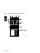
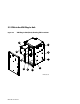
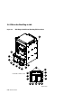

FRU Locations 5-5
1
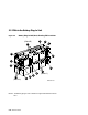
70–28574–01 LSB centerplane and card cage
1, 2
2
E2044–AA IOP module
3
E2043–AA or
E2043–BA or
E2043–CA or
E2046–AA
Memory module 64 Mbytes
3
Memory module 128 Mbytes
3
Memory module 256 Mbytes
3
Memory module 512 Mbytes
3
4
54–20300–01 Cabinet control logic module (CCL)
5
54–36203–04 CCL pressure sensor
6
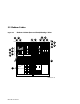
TF85–AA Removable media device
1
Includes these FRUs:
TK85
54–19089–01
54–20868–01
17–03123–01
17–03164–01
17–03348–01
17–03443–01
17–03444–01
17–03448–01
17–03505–01
17–03508–01
Disk drive
DSSI controller module
Local disk converter
LDC to CCL signal
LDC to TF power +5/+12
DSSI signal to bulkhead (TK85)
Power LDC to bulkhead
Signal LDC to bulkhead
DSSI bus TF to bulkhead
5V VTERM power
48V power regulator to bulkhead
7
30–35143–01 DC distribution box
8
30–33798–01 or
30–33798–02 or
30–33798–03
AC input box
9
12–35173–01 Blower
1
10
DWLMA–AA/BA XMI plug-in unit
1
(see page 5-8)
11
BA654–AA Disk plug-in unit
3, 4
(see page 5-10)
12
H7237–AA Battery plug-in unit
1
(see page 5-12)
1
Removal and replacement of this FRU requires access to both the front and the rear of th
e
cabinet.
2
This FRU is in the main cabinet only (cannot be located in the expander cabinet).
3
This FRU can be located in either the front or the rear of the cabinet.
4
This FRU can be located in the top portion (front or rear) only in the expander cabinet.