
User`s guide

System Initialization and Acceptance Testing (Normal Operation)
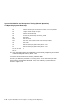
4.7 Operating System Bootstrap
R0 Address of descriptor of boot device name; 0 if none specified
R2 Length of PFN bitmap in bytes
R3 Address of PFN bitmap
R4 Time-of-day of bootstrap from PR$_TODR
R5 Boot flags
R10 Halt PC value
R11 Halt PSL value (without halt code and map enable)
AP Halt code
SP Base of 128-Kbyte good memory block + 512
PC Base of 128-Kbyte good memory block + 512
R1, R6, R7, R8,
R9, FP
0
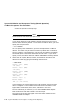
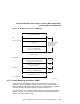
10. Copy the VMB image from FEPROM to local memory beginning at the base
of the 128 KB good memory block + 512.
11. Exit from the firmware to memory resident VMB.
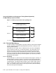
On entry to VMB the processor is running at IPL 31 on the interrupt stack
with memory management disabled. Also, local memory is partitioned as
shown in Figure 4–3.
4–22 System Initialization and Acceptance Testing (Normal Operation)