
User`s guide


System Initialization and Acceptance Testing (Normal Operation)
4.6 Main Memory Layout and State
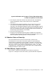
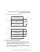
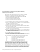
Figure 4–2 Memory Layout After Power-Up Diagnostics
Available system memory
(pages potentially good or bad)
PFN bitmap
(always on page boundary and
size in pages n = (# of MB )/2)
Firmware "scratch memory"
(always 16 KB)
Q22-Bus Scatter/Gather Map
(always on 32 KB boundary)
Potential "bad" memory
.
.
.
.
.
.
.
.
.
.
PFN bitmap
QMR base
Top of Memory
n pages
32 pages
64 pages
0
MLO-008454
4.6.1 Reserved Main Memory
In order to build the scatter/gather map and the bitmap, the firmware attempts
to find a physically contiguous page-aligned 1M byte block of memory at the
highest possible address.
Of the 1M byte, the upper 32 KB is dedicated to the Q22–bus scatter/gather
map, as shown in Figure 4–2. Of the lower portion, up to 32K bytes at the
bottom of the block is allocated to the Page Frame Number (PFN) bitmap.
The size of the PFN bitmap is dependent on the extent of physical memory.
Each bit in the bitmap maps one page (512 bytes) of memory. The remainder
of the block between the bitmap and scatter/gather map (minimally 16 KB) is
allocated for the firmware.
4.6.1.1 PFN Bitmap
The PFN bitmap is a data structure that indicates which pages in memory are
deemed usable by operating systems. The bitmap is built by the diagnostics
as a side effect of the memory tests on power-up. The bitmap always starts on
a page boundary. The bitmap requires 1 KB for every 4 MB of main memory,
hence, a 8 MB system requires 2 KB, 16 MB requires 4 KB, 32 MB requires
8 KB, and a 64 MB requires 16 KB. There may be memory above the bitmap
which has both good and bad pages.
4–18 System Initialization and Acceptance Testing (Normal Operation)