
User`s guide

System Initialization and Acceptance Testing (Normal Operation)
4.4 Basic Acceptance Test Procedure
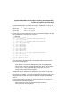
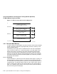
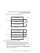
Examine MEMCON 0–1 to verify the memory configuration. Each pair of
MEMCONs maps one memory module as follows:
MEMCON0 Set 0; 0A, 0B, 0C, 0D
MEMCON1 Set 1; 1E, 1F, 1G, 1H
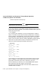
2. Check the Q22–bus and the Q22–bus logic in the KA52/53 CQBIC chip and
the configuration of the Q22–bus, as follows:
>>>SHOW QBUS
Scan of Q-bus I/O Space
-200000DC (760334)=0000 RQDX3/KDA50/RRD50/RQC25/KFQSA-DISK
-200000DE (760336)=0AA0
-20001468 (772150)=0000 RQDX3/KDA50/RRD50/RQC25/KFQSA-DISK
-2000146A (772152)=0AA0
-20001920 (774440)=FF08 DESQA
-20001922 (774442)=FF00
-20001924 (774444)=FF2B
-20001926 (774446)=FF09
-20001928 (774450)=FFA3
-2000192A (774452)=FF96
-2000192C (774454)=0050
-2000192E (774456)=1030
-20001940 (774500)=0000 TQK50/TQK70/TU81E/RV20/KFQSA-TAPE
-20001942 (774502)=0BC0
-20001F40 (777500)=0020 IPCR
Scan of Q-bus Memory Space
>>>
The columns are described below. The examples listed are from the last
line of the example above.
First column = the VAX I/O address of the CSR, in hex (20001F40).
Second column = the Q22–bus address of the CSR, in octal (777500).
Third column = the data, contained at the CSR address, in hex (0020).
Fourth column = the speculated device name (IPCR, the CPU
interprocessor communications register).
Additional lines for the device are displayed if more than one CSR exists.
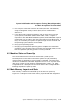
The last line, Scan of Q–bus Memory Space, displays memory residing on
the Q22–bus, if present. VAX memory mapped by the Q22–bus map is not
displayed under SHOW QBUS, but is displayed using SHOW MEMORY
/FULL.
If the system contains an MSCP or TMSCP controller, run test 81. This
test performs the following functions:
Performs step one of the UQ port initialization sequence
Performs the SA wraparound test
System Initialization and Acceptance Testing (Normal Operation) 4–15