
User`s guide

System Initialization and Acceptance Testing (Normal Operation)
4.4 Basic Acceptance Test Procedure
4.4 Basic Acceptance Test Procedure
Perform the acceptance testing procedure listed below, after installing a
system, or whenever adding or replacing the following:
CPU module
MS44 memory SIMM
DSSI device
SCSI device
SYNC device
ASYNC device
1. Run two error-free passes of the power-up scripts by entering the following
command:
>>>TB5
Script B5 will halt on an error so that the error message will not scroll off
the screen.
Press
Ctrl/C
to terminate the scripts. Refer to Chapter 5 if failures occur.
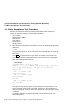
To check the memory configuration and to ensure there are no bad pages,
enter the following command line:
>>>SHOW MEM/FULL
16 MB RAM, SIMM Set (0A,0B,0C,0D) present
Memory Set 0: 00000000 to 00FFFFFF, 16MB, 32768 good pages, 0 bad pages
Total of 16MB, 32768 good pages, 0 bad pages, 104 reserved pages
Memory Bitmap
-00FF3000 to 00FF3FFF, 8 pages
Console Scratch Area
-00FF4000 to 00FF7FFF, 32 pages
Scan of Bad Pages
Q-bus Map
-01FF8000 to 01FFFFFF, 64 pages
Scan of Bad Pages
>>>
The Q22–bus map always spans the top 32 Kbytes of good memory. The
memory bitmap always spans two pages (1 Kbyte) for each 4 Mbytes of
memory configured. Each bit within the memory bit map represents a page
of memory.
To identify registers and register bit fields, see the KA52/53/54 CPU
Technical Manual.
4–14 System Initialization and Acceptance Testing (Normal Operation)