
User`s guide

KA52/53/54 CPU Module Description
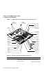
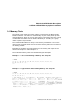
1.2 MS44 and MS44L Memory Modules
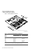
Figure 1–4 Memory Expansion Connectors
GA_EN00083A_92A
1G
0C
1E
0B
1F
0D
1H
0A
Note: 0A 0B 0C and 0D are identifiers for the basic system memory connectors.
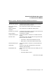
Table 1–2 KA52/53/54 CPU Module Memory Configurations
Total
Increment 1
1
Increment 2
Memory (0A + 0B + 0C + 0D)
2
(1E+1F+1G+1H)
2
(bytes)
16M MS44L-BC
32M MS44L-BC MS44L-BC
64M MS44-DC
80M MS44-DC MS44L-BC
128M MS44-DC MS44-DC
1
Basic system memory.
2
0A, 0B, 0C, 0D, 1E, 1F, 1G, and 1H are connector identifiers (see Figure 1–4).
1–10 KA52/53/54 CPU Module Description