
User`s guide

KA52/53/54 CPU Module Description
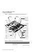
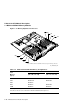
1.1 KA52/53/54 CPU Module
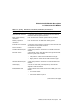
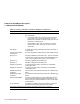
Table 1–1 (Cont.) Functions of Controls, Indicators, Connectors
Component Description
Break/Enable switch
1
A two-position switch that determines the function of MMJ
port 3 as follows:
• Up position—MMJ port 3 functions as a console port.
In this state, you can press the Break key on the
keyboard of a terminal connected to MMJ port 3 to put
the system in console mode.
• Down position—MMJ port 3 functions as a normal
communications port. MMJ port 0 functions as the
console port.
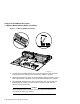
Halt button A momentary-contact push button that puts the system in
console mode.
Asynchronous modem
control port 2
EIA-232 compatible asynchronous port with modem control.
MMJ port 3 DEC423 compatible asynchronous port. This port functions
as the primary console port when the Break/Enable switch
is set to the up position when you turn on the system.
MMJ port 1 DEC423 compatible asynchronous port.
MMJ port 0 DEC423 compatible asynchronous port.
DSW42 I/O connector A connector that provides a connection for the DSW42
input/output cable.
DHW42 I/O connector A connector that provides a connection for the DHW42
input/output cable.
DSW42 logic board
connectors
Two connectors that provide connections for a DSW42 logic
board.
DHW42 logic board
connectors
Two connectors that provide connections for a DHW42 logic
board.
DSSI connector/board Connector provides physical interface between the board
and the internal and external DSSI storage devices. The
board is the logic interface between the CPU and the DSSI
storage devices.
Q–bus connector An expansion capability only that provides the interface
between the CPU and the external Q–bus devices.
1
The system recognizes the position of this switch only when the system is turned on.
1–8 KA52/53/54 CPU Module Description