
User`s guide

KA52/53/54 CPU Module Description
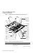
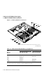
1.1 KA52/53/54 CPU Module
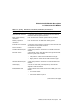
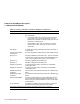
Table 1–1 (Cont.) Functions of Controls, Indicators, Connectors
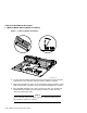
Component Description
Internal SCSI connector A connector that provides a connection for SCSI devices
mounted inside the system enclosure.
Basic system memory
connectors
Four connectors for the basic system memory modules.
Memory expansion
connectors
Four connectors for an additional memory option.
External SCSI connector A connector that provides a connection to SCSI devices that
are external to the system enclosure.
Power connector A connector for dc power.
ThinWire Ethernet port A port that provides a connection to a ThinWire Ethernet
network.
Ethernet switch A two-position switch that determines the type of Ethernet
that the system uses as follows:
• Left position—selects the standard Ethernet type
• Right position—selects the ThinWire Ethernet type
Standard Ethernet port A port that provides a connection to a standard Ethernet
network.
LED display A set of six LEDs that provide power-up and self-test
diagnostic code information.
Break/Enable LED A LED indicator that shows the function of MMJ port 3 as
follows:
• On—Break enable
• Off—Break disable on port 3
(continued on next page)
KA52/53/54 CPU Module Description 1–7