
User`s guide

Data Structures and Memory Layout
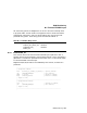
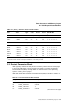
C.1 Halt Dispatch State Machine
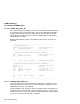
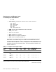
Table C–1 (Cont.) Firmware State Transition Table
Current
State
Next
State
Halt
Type
Halt
Code
Mailbx
Action
User
Action
HEN-ERR-TIP-
DIP-BIP-RIP
Perform common exit processing, if no errors
7
RESTART –>EXIT xxx xx xx xxx x - 0 - x - x - x - x
HALT –>EXIT xxx xx xx xxx x - 0 - x - x - x - x
Exception transitions, just halt
8
INIT –>HALT xxx xx xx xxx x - x - x - x - x - x
BOOT –>HALT xxx xx xx xxx x - x - x - x - x - x
REST –>HALT xxx xx xx xxx x - x - x - x - x - x
HALT –>HALT xxx xx xx xxx x - x - x - x - x - x
TRACE –>HALT xxx xx xx xxx x - x - x - x - x - x
EXIT –>HALT xxx xx xx xxx x - x - x - x - x - x
7
Exit after halts, bootstrap or restart. The exit state transitions to program I/O mode.
8
Guard block that catches all exception conditions. In all cases, just halt.
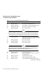
C.2 Restart Parameter Block
VMB typically utilizes the low portion of memory unless there are bad pages
in the first 128K bytes. The first page in its block is used for the Restart
Parameter Block (RPB), through which it communicates to the operating
system. Usually, this is page 0.
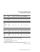
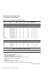
VMB will initialize the Restart Parameter Block (RPB) as shown in Table C–2.
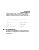
Table C–2 Restart Parameter Block Fields
(R11)+ Field Name Description
00: RPB$L_BASE Physical address of base of RPB.
04: RPB$L_RESTART Cleared.
08: RPB$L_CHKSUM -1
0C: RPB$L_RSTRTFLG Cleared.
(continued on next page)
Data Structures and Memory Layout C–5