
User`s guide


ROM Partitioning
B.1 Firmware EPROM Layout
By convention, all VAX 4000 systems implement a longword at physical
location 20040004 in the firmware FEPROM for the SIE. The layout of the SIE
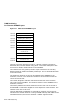
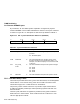
is shown in Figure B–3. A description of each field is provided in Table B–2.
Figure B–3 SIE : System Identification Extension (20040004)
31
00
0708
15
16
23
24
MLO-007700
SYS_TYPE
Version SYS_SUB_TYPE
Variant
Table B–2 System Identification Extension
Field Name RW Description
31:24 SYS_TYPE ro This field identifies the type of system for a specific
processor.
03 : Bounded system.
23:16 VERSION ro This field indentifies the resident version of the
firmware encoded as two hexadecimal digits. For
example, if the banner displays V5.0, then this field
is 50 (hex).
15:8 SYS_SUB_
TYPE
ro This field indentifies the particular system subtype.
08 : KA50
09 : KA51
0A : KA52
0B : KA53
7:0 VARIANT ro This field indentifies the particular system variant.
B.1.2 Call-Back Entry Points
The firmware provides several entry points that facilitate I/O to the designated
console device. Users of these entry points do not need to be aware of the
console device type, be it a video terminal or workstation.
The primary intent of these routines is to provide a simple console device
to VMB and secondary bootstraps, before operating systems load their own
terminal drivers.
These are JSB (subroutine as opposed to procedure) entry points located in
fixed locations in the firmware. These locations branch to code that in turn
calls the appropriate routines.
B–4 ROM Partitioning