
User`s guide


System Troubleshooting and Diagnostics
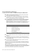
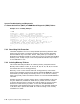
5.3 Power-On Self-Test (POST) and ROM-Based Diagnostic (RBD) Failures
Note
Do not confuse the countdown pattern of powerup tests with the test
number. In the following the last countdown was 58; this number
should not be reported! The test number was 31.
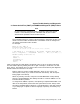
The countdown pattern is used to indicate progress in the power-up tests. The
actual true test number associated with a countdown value can change from
one release of the ROM code to another.
For example:
KA52-A T1.2-156, VMB 2.14
Performing normal system tests.
72..71..70..69..68..67..66..65..64..63..62..61..60..59..58..
? Test_Subtest_31_06 Loop_Subtest=05 Err_Type=FF DE_Memory_Setup_CSRs.lis
Vec=0000 Prev_Errs=0000 P1=C94AC94A P2=01000000 P3=00000002 P4=00000000
Minimum recording for this error is:
Test = 31
Subtest = 6
Loop_subtest = 5
Err_type = FF
Vec = 0.
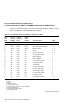
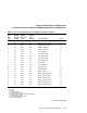
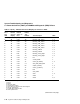
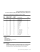
Table 5-4 lists the hex LED display, the default action on errors, and the most likely
unit that needs replacing reading from left to right. Example, 1,4 indicates 1 is most
likely, then 4. The Default on Error column refers to the action taken by the diagnostic
executive when the test fails in the script.
Memory tests are usually treated differently; when an error occurs, the
memory tests usually try to continue and mark the bitmap. Test 40 reports
failing pages in the bitmap.
When any memory test fails, always do a SHOW MEMORY to help identify
the FRU. SHOW MEMORY will identify the FRU to a SET of SIMMs or to an
individual SIMM if possible.
If a single set of SIMMs is present, and replacing a suspected bad SIMM or set
does not fix the problem, assume that the system board is bad. Always check
the seating of SIMMs before replacing. If nonvolatile data is lost after powerup
or you always get a request to select a language at powerup, the battery may
be bad.
System Troubleshooting and Diagnostics 5–43