
User`s guide


System Initialization and Acceptance Testing (Normal Operation)
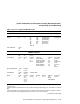
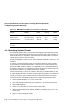
4.7 Operating System Bootstrap
available (unmapped to other devices) for proper operation. After a successful
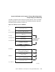
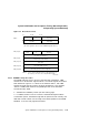
bootstrap operation, control is passed to the secondary bootstrap image with
the memory layout as shown in Figure 4–4.
Figure 4–4 Memory Layout at VMB Exit
PFN bitmap
(always on page boundary and
size in pages n = (# of MB )/2)
Firmware "scratch memory"
(always 16 KB)
Q22-Bus Scatter/Gather Map
(always on 32 KB boundary)
Potential "bad" memory
.
.
.
.
.
.
.
.
PFN bitmap
QMR base
Top of Memory
n pages
32 pages
64 pages
0
VMB image
Reserved for RPB, initial stack
Base
Base+512(SP,PC)
256 pages for VMB
128 KB block of
"good" memory
(page aligned)
MLO-008456
Unused memory
Potential "bad" memory
SCB (2 pages)
Stack (3 pages)
Secondary bootstrap image
(potentially exceeds block)
Next page
Next page+1024
Next page+2560
..
System Initialization and Acceptance Testing (Normal Operation) 4–25