Mitsubishi Netcom 2 User Manual Version 5.
Table of Contents 1. What is a Netcom? .......................................................................................................... 3 2. Who do I Contact For Technical Support? ..................................................................... 3 3. What are the System Requirements for Netcom? ........................................................... 3 3.1 Operating System Requirements................................................................................... 3 3.
7.24 Preferences/ Preferences Page .................................................................................. 48 7.25 Restart/Restart Page .................................................................................................. 49 APPENDIX A RJ45 to DB9 pin out ................................................................................. 50 APPENDIX B 9700 and 2033A connection ..................................................................... 51 APPENDIX C SEC connections...........
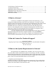
The remote shutdown agents will run on the following operating systems: 3.
Additional to the above listed OS, the following listed RCCMD versions are available From Mitsubishi. Please contact Mitsubishi for the following; VMWARE Sphere ESX 4 i VMWARE ESX Server 3.5x / 4 (VMWare certified) CITRIX XEN Server 4.5 and 5.5 and higher (Citrix certified) MICROSOFT HYPER-V 2008 CENTOS INTEL x86, x64 & IA64 CPU LINUX PowerPC CPU LINUX ITANIUM X64 CPU LINUX SUSE 6.3x APX ALPHA CPU HP UNIX 9 PA-RISC CPU HP UNIX V 11.2x, 11.3x SPARC & ITANIUM 64 CPU QNX 4 and QNX 6 on X86 MAC OS X 10.1-10.
3.7 No longer supported UPSMAN versions (please choose RCCMD instead) : DEC ULTRIX, HP UNIX 9 PA-RISC CPU, IBM OS/2 Version WARP 4.0 X86 CPU, IBM OS/2 Version LAN SERVER 3.0, 4.0, 5.0 INTEL CPU, IBM OS/2 SNMP sub-agent, IBM AIX V 3.25, IBM AIX 4.1, WINDOWS NT 3.51 INTEL CPU, WINDOWS NT 3.51 ALPHA CPU, NOVELL NetWare 3.11 and 3.12 INTEL CPU, INTERACTIVE UNIX 3.2, VMS 5.5 for VAX or ALPHA, SUN SOLARIS 2.5, LINUX SUSE 5.x and 6.x. WINDOWS NT 4.0 ALPHA CPU, DEC OPEN VMS on VAX CPU, V.5x, V.6x, V.
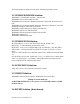
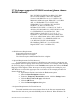
Service Pack 2 is installed on a computer it will turn on the personal firewall. Below are the steps to open up the web port for Netcom in Windows XP Firewall: Select Start Menu > Control Panel. Select Network Connections and right click on the connection that is being used. Click on Properties and click the Advanced tab in the Properties dialogue. Press the Settings... button to bring up the Firewall dialogue. Go to the Exceptions tab and click the Add Port button.
2. Open a HyperTerminal session by selecting (Installed location may vary) Start > All Programs > Accessories > Communications > HyperTerminal. 3. Select an available communications port from the drop-down list. 4. Select the following port settings: Bits per second: 19200 Data bits: 8 Parity: None Stop bits: 1 Flow Control: None 5. Cycle power from the Netcom by pulling out the power connector and reinserting. 6. Wait for > and type test, this must be done within five seconds.
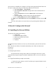
3. On the PC that the cross over cable is connected to, select ,“Control Panel”, “Network Connections”. Right click on “Local Area Connection” and select “Properties”. 4. Double click “Internet Protocol (TCP/IP)”.
5. Select “Use the Following IP address:” 6. Enter; IP address: 192.168.0.1 Subnet mask: 255.255.255.0 Default gateway: 192.168.0.
7. Click on the “Internet Protocol (TCP/IP) Properties” screen. 8. Click on the “Local Area Connection Properties” screen. 9. Click on . 10. Select . 11. Enter: http://192.168.0.253, and click OK. 12. The Netcom2 log in screen will appear.
13. If the Netcom log in screen does not appear perform the following; a. Verify the cross over cable is connected to the Netcom2 port labeled “Network” b. Verify the power light on the Netcom2 is green and the status light is blinking. c. Ping the entered IP address in the DOS prompt. d. Verify the “local area connection” is connected in the Network connections screen 14. The default login and password of a Netcom is; Username: admin Password: admin 15.
17. Once the “Save” button is selected you will be presented with the following screen. Selecting OK will write the IP address to the memory of the Netcom. You will no longer be able to communicate with the Netcom at the default IP address. **If the Netcom2 is going to be connected to a 2033A or 9700 the protocol will have to be changed using the DB9 connector supplied with the Netcom2. Please refer to the step 4.2.1. 4.2.3 Configuring the IP address with Windows 7 1.
4. Select Control Panel. 5. Under “Network and Internet” select “view network and status tasks”. 6. In the “Network and sharing center” double click on the “local Area Connection”. . 7. In the “local Area Connection Status” select . 8. Double click on 9. Select the “Use the Following IP address” radio button. 10. Enter the following information; IP Address: 192.168.0.1 Subnet Masks: 255.255.255.0 Default gateway: 192.168.0.
11. Click ok. 12. Click ok, on the Local Area Connection Properties. , in the “Search programs and files” enter “run”. 13. Select 14. Select run. 15. Enter: http://192.168.0.253 16. If the Netcom log in screen is present skip to step 17, if the screen does not appear perform the following; e. Verify the cross over cable is connected to the Netcom2 port labeled “Network” f. Verify the power light on the Netcom2 is green and the status light is blinking. g. Ping the entered IP address in the DOS prompt h.
19. The user will be able to change the IP information from this screen. After the IP information has been entered the “Save” button must be selected for the information to be saved. 20. Once the “Save” button is selected you will be presented with the following screen. Selecting OK will write the IP address to the memory of the Netcom. You will no longer be able to communicate with the Netcom at the default IP address. 21.
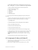
5. How do I Update the Netcom Firmware? Configuration Upgrade. The Netcom2 is shipped with firmware installed, if needed the latest firmware version is available for download at; www.meppi.com/Products/UninterruptiblePowerSupplies/Communication. The firmware version installed in the Netcom2 can be found in the log in screen under the user name and password. 5.1. Open “SineticaTFTPclient.exe” on the Netcom CD. Figure 5.
5.2. In the 'File Settings' group select 'APPLICATION UPGRADE' from the 'File Transfer Type' drop down list. 5.3. In the 'Download File Name' edit box select the name of the file, XX.XX.X.bin, supplied on the Netcom 2 CD. 5.4. In the ‘TFTP Settings’ group enter the required IP address of the unit to be upgraded in the ‘IP Address’ box. 5.5. Click the 'DOWNLOAD TO DEVICE' button. A blue task bar will flow from left to right and data information will be displayed in the information box.
6. Netcom Web Server Before attempting to connect to the Netcom2 for the first time check the following; 1. An IP address has been assigned 2. The supplied RJ45 to DB9 cable is connected to the port labeled UPS and connected to the UPS communication port (contact Mitsubishi or your local service group) 3. The intranet cable is connected to the Network plug and the amber and green lights are flashing 4. Power is applied to the Netcom and the power and status lights are on. 5.
7.1 Login Page Figure 7 After connecting to the Netcom Figure 2 will be displayed, the default password for the Netcom is: Username: admin Password: admin The Netcom2 Firmware version is located under the Serial number; the most current software version can be downloaded at Meppi.com. The default password and login for the Netcom is admin, admin. If the password is changed and lost the following steps will need to be completed to reset the password; 1. 2. 3. 4. 5. 6. 7.
7.2 UPS Status Page/ UPS/ Overview Figure 7.1 When the Netcom is initially powered on the user will be taken to the over view screen, pictured below in figure 7.2. The user must select Setup at the top of the screen and select Preferences on the left side of the screen to be directed to figure 7.2. Figure 7.
Under the default, select UPS ->Status this will set the status page to default. The user can also select the time before the Netcom2 times out by selecting the User Session Timeout: drop down. If the Input Volts, Output volts, or Output load is any color other than green the values are out of limits. This can be corrected by entering the correct values in the Nominal Values page or the values are out of the UPS’s operating range.
7.3 Identification/UPS Identification Page Figure 7.3 Click on the Identification menu option to display the UPS serial number, contact name, contact email, contact phone number and battery information. This information is input at the Agent Setup menu (see figure 7.7).
7.4 Variables/Variables Page Figure 7.4 Click the Variables page to display the variables page. This page displays a list of the available UPS variables. The variables displayed may vary depending on the unit that is being monitored.
7.5 Event Log/View Events Page Figure 7.5 Click on the Event Log menu option to display the View/Events page. The event log will hold the latest events received from the UPS. The events can be sorted by month, year and order of occurrence by selecting the View Event. When an event occurs, it will be written to the event log with a date/time stamp. When the event is cleared (alarm removed), it will be written to the event log in the format “event removed”, where event is the name of the event being cleared.
7.6 Agent Setup/UPS/Configuration Page Figure 7.6 The Agent Setup (Netcom) page is where the UPS name, serial number, contact name, contact email, and contact phone number can be inserted. The battery install date is inserted into this field for battery age calculation that is available on the UPS/Identification page. The battery install date will also vary depending on the date that is selected in the SETUP/ Time Settings page.
7.7 Nominal Values/UPS Nominal Values Page Figure 7.7 The UPS/Nominal Values page is where the UPS nominal values can be changed. This information can be found in the UPS Owners/Technical for nominal values. If these values are not set to the current UPS values the UPS Status values will not read correctly and the bar graphs will not indicate proper voltage. When the words Change Nominal Values is selected the user is directed to figure 7.8. The UPS nominal values are entered into this screen and saved.
7.8 Nominal Values/UPS Nominal Values Setup Figure 7.
7.9 Shutdown/UPS Shutdown Setup Page Figure 7.9 Figure 7.9 is an example of the UPS/Shutdown Configuration page. In this page the user can select the UPS activity that will trigger a shut down message, by enabling a parameter the user can send a shut down on; 1. Battery Capacity percentage, when the UPS detects the percentage of battery remaining a shutdown will be initiated after the time limit has elapsed. 2.
9. Input Out of Range, when the UPS input voltage deviates from the UPS’s operating parameters a shut down message will be sent after the preset time limit has been reached. 10. Overload, when the unit is overload and the preset timer has expired a shut down message will be sent. 11. Temperature Out of Range, when the UPS experiences temperature that exceed the operating standards and the timer has elapsed a shut down message will be sent. Each parameter has a time limit or percentage attached to it.
Note: Not all UPS support the estimated runtime variable. -On Battery – Click the On Battery radio button. When the UPS goes on battery, a shutdown message will be sent to all listed systems.
7.11Overview/Network Setup Page Figure 7.11 The Network Setup/Overview page displays the systems name, MAC address, serial number, firmware version, System uptime, IP information and user information.
7.12 IP Config/Setup/IP Configuration Page Figure 7.12 At the Setup/ IP Configuration page the System name, IP address, Subnet Mask, Gateway, and Config Protocol can be change. The name that will appear in the upper right hand of ALL screens is set in the System Name box. Check with your IT administrator for recommended settings. The Config Protocol can be set to static, Dynamic Host Configuration Protocol (DHCP) or Bootstrap Protocol (Bootp) by using the drop down box.
7.13 HTTP/HTTP Setup Page Figure 7.13 The HTTP protocol function can be set by selecting the radio button. The unsecured port can be changed, but check with your IT administration and Network firewalls for proper settings.
7.14 LDAP Servers/Setup/LDAP Servers Page Figure 7.14 Lightweight Directory Access Protocol (LDAP) has four options that are enabled by the drop down box and two optional servers. The drop down box has Disable, Primary, Secondary, and both. Your IT administration will be able to provide the necessary information for this function to be used if needed.
7.15 SNMP NMS/Setup SNMP Page Figure 7.15 The Setup/SNMP NMS function is used to set up the network management station that will be viewing the UPS information using GETs and SETs. The Get operation is used by the NMS to obtain the necessary information and the SETs command are used to configure the management device for the information. The network management stations that must access the units SNMP function must be entered at this page. For each Network Management Station the following must be entered.
7.16 SNMP Rec’rs/SNMP Receivers Page Figure 7.16 The Setup/SNMP Rec’rs page is used to set up the community receivers. The IP address, community string and access permissions are specified here for up to ten Network Management Stations. Any machine which will be required to receive SNMP traps sent from this unit must be entered here. This page will change be changed if entries are made on the Event Notification page.
7.17 Event Notification/Event Notification Figure 7.17 The UPS/Event Notifications screen can be customized by the user is several ways. The user can build their own categories in the User Defined 1 and User Defined 2 fields. Once a name/group is entered in the selected user define field and the page is saved the name/group will populate next to the information box. When a name/group is selected the user will be directed to figure 7.18.
Figure 7.18 In this screen the user can assign event codes to one group by selecting the radio buttons. An event can only be assigned to one group, if the None is selected the alarm will not be sent out to any group. After assigning and event to a group click the save button. If the word E-mail is selected the user will be directed to the Setup Email Alerts page displayed in figure 7.19.
Figure 7.19 In this screen the user can enter the email addresses of the individual/groups emails. Any changes made to this screen will affect the Email Alerts and SNMP (receivers) pages. The SMTP server address must be entered and the Enable check box must be selected for e-mails. The delay timer will start when an e-mail able event occurs; if the event clears before the timer expires an email will NOT be sent.
Figure 7.20 In figure 7.20 the user has the ability to input 10 trap receivers per event category. The trap community string must be entered for messages to be transmitted. The categories are selected in figure one of this section and an event can only be used in one category. After all receivers are entered, enabled and saved a test call can be made by selecting the Test All button.
Figure 7.21 In figure 7.21 the user has the ability to redefine the event messages that are displayed in the body of the email. After changes are entered or changed the save button must be selected. If the event name is not change the default event type will be sent out.
7.19 Users/Setup/Users Figure 7.22 The Netcom has three security levels that can be selected; Administrator, controller, and viewer. Administrator allows the user full access to the Netcom and the ability to make changes and send test emails and shutdowns. Controller and Viewer allow the user to view the information only.
7.20 Email Alerts/ Setup/ Email Alerts Figure 7.23 In this screen the user can enter the email addresses of the individual/groups emails. Any changes made to this screen will affect the Email Alerts and SNMP (receivers) pages. The SMTP server address must be entered and the Enable check box must be selected for e-mails. The delay timer will start when an e-mail able event occurs; if the event clears before the timer expires an email will NOT be sent.
7.21 Time Setting/ Setup/ Time Settings Figure 7.24 This screen is used to set the time and date.
7.22 Syslog Servers/ Setup/ Syslog Servers Figure 7.25 The Syslog Servers it not currently used in the Netcom2 and is not currently supported by Mitsubishi.
7.23 Events/ View/ Events Figure 7.26 In the events page the user can view the past UPS events that were recorded by the Netcom. The user has the ability to view a specific month in a year by using the drop down boxes.
7.24 Preferences/ Preferences Page Figure 7.27 The Setup/Preferences page is used to set the default page of the Netcom. This page allows the user to set the page that will be displayed after the initial log in session. The default page and user session timeout options are set using the drop down box. The temperature scale option is a function not used by the UPS.
7.25 Restart/Restart Page Figure 7.28 The restart function will reset the unit’s runtime and will restart the Netcom. The reset to factory defaults will reset many of the Netcom’s setting, if this option must be performed record all values. The IP address will have to be reset when resetting to factory defaults, but the Netcom will allow access one time after the reset to set the IP information.
APPENDIX A RJ45 to DB9 pin out Appendix A: RJ45 to DE9 connection RS232 Wiring Connections: Netcom-2 to PC Com Port.
APPENDIX B 9700 and 2033A connection SVA026 Netcom 2 User Manual ver5 51
APPENDIX C SEC connections SVA026 Netcom 2 User Manual ver5 52
APPENDIX D MIBS Appendix B: MIB file -- Mitsubishi.mib - MIB file for Mitsubishi UPSs UPS-MIB DEFINITIONS ::= BEGIN IMPORTS TRAP-TYPE FROM RFC-1215 DisplayString FROM RFC1213-MIB OBJECT-TYPE FROM RFC-1212 Gauge, Counter, TimeTicks, mgmt FROM RFC1155-SMI ; PositiveInteger NonNegativeInteger TimeStamp TimeInterval TestAndIncr AutonomousType Tag MitsubishiUPS ::= ::= ::= ::= ::= ::= INTEGER INTEGER TimeTicks INTEGER (0..2147483647) INTEGER (0..
DESCRIPTION "The UPS Model designation." ::= { upsIdent 2 } upsIdentUPSSoftwareVersion OBJECT-TYPE SYNTAX DisplayString ACCESS read-only STATUS mandatory DESCRIPTION "The UPS firmware/software version(s). This variable may or may not have the same value as upsIdentAgentSoftwareVersion in some implementations." ::= { upsIdent 3 } upsIdentAgentSoftwareVersion OBJECT-TYPE SYNTAX DisplayString ACCESS read-only STATUS mandatory DESCRIPTION "The UPS agent software version.
"The indication of the capacity remaining in the UPS batteries. A value of batteryNormal indicates a normal battery condition. A value of batteryLow indicates the remaining battery runtime will not maintain the output load for an extended period of time. A value of batteryDepleted indicates that the UPS will be unable to sustain the present load when and if the utility power is lost.
::= { upsBattery 5 } upsBatteryCurrent OBJECT-TYPE SYNTAX INTEGER (-2147483648..2147483647) -- UNITS 0.1 Amp DC ACCESS read-only STATUS mandatory DESCRIPTION "The present battery current (0.1 Amp DC)." ::= { upsBattery 6 } upsBatteryTemperature OBJECT-TYPE SYNTAX INTEGER (-2147483648..2147483647) -- UNITS degrees Centigrade ACCESS read-only STATUS mandatory DESCRIPTION "The ambient temperature at or near the UPS Battery casing (degrees Centigrade).
"An entry containing information applicable to a particular input line." INDEX { upsInputLineIndex } ::= { upsInputTable 1 } UpsInputEntry ::= SEQUENCE { upsInputLineIndex upsInputFrequency upsInputVoltage upsInputCurrent upsInputTruePower } PositiveInteger, NonNegativeInteger, NonNegativeInteger, NonNegativeInteger, NonNegativeInteger upsInputLineIndex OBJECT-TYPE SYNTAX PositiveInteger ACCESS read-only STATUS mandatory DESCRIPTION "The input line identifier.
upsOutputSource OBJECT-TYPE SYNTAX INTEGER { other(1), none(2), normal(3), bypass(4), battery(5), booster(6), reducer(7) } ACCESS read-only STATUS mandatory DESCRIPTION "The present source of output power. A value of none (2) indicates there is no source of output power (and therefore no output power), for example, the system has opened the output breaker." ::= { upsOutput 1 } upsOutputFrequency OBJECT-TYPE SYNTAX NonNegativeInteger -- UNITS 0.
UpsOutputEntry ::= SEQUENCE { upsOutputLineIndex upsOutputVoltage upsOutputCurrent upsOutputPower upsOutputPercentLoad } PositiveInteger, NonNegativeInteger, NonNegativeInteger, NonNegativeInteger, INTEGER upsOutputLineIndex OBJECT-TYPE SYNTAX PositiveInteger ACCESS read-only STATUS mandatory DESCRIPTION "The output line identifier." ::= { upsOutputEntry 1 } upsOutputVoltage OBJECT-TYPE SYNTAX NonNegativeInteger -- UNITS 0.
STATUS mandatory DESCRIPTION "The present bypass frequency." ::= { upsBypass 1 } upsBypassNumLines OBJECT-TYPE SYNTAX NonNegativeInteger ACCESS read-only STATUS mandatory DESCRIPTION "The number of bypass lines utilized in this device. This entry indicates the number of rows in the bypass table." ::= { upsBypass 2 } upsBypassTable OBJECT-TYPE SYNTAX SEQUENCE OF UpsBypassEntry ACCESS not-accessible STATUS mandatory DESCRIPTION "A list of bypass table entries.
upsBypassCurrent OBJECT-TYPE SYNTAX NonNegativeInteger -- UNITS 0.1 RMS Amp ACCESS read-only STATUS mandatory DESCRIPTION "The present bypass current (0.1 RMS Amp)." ::= { upsBypassEntry 3 } upsBypassPower OBJECT-TYPE SYNTAX NonNegativeInteger -- UNITS Watts ACCESS read-only STATUS mandatory DESCRIPTION "The present true power conveyed by the bypass (watts).
UpsAlarmEntry ::= SEQUENCE { upsAlarmId upsAlarmDescr upsAlarmTime } PositiveInteger, AutonomousType, TimeStamp upsAlarmId OBJECT-TYPE SYNTAX PositiveInteger ACCESS read-only STATUS mandatory DESCRIPTION "A unique identifier for an alarm condition. value must remain constant." ::= { upsAlarmEntry 1 } This upsAlarmDescr OBJECT-TYPE SYNTAX AutonomousType ACCESS read-only STATUS mandatory DESCRIPTION "A reference to an alarm description object.
upsWellKnownAlarms OBJECT IDENTIFIER ::= { upsAlarm 3 } upsAlarmBatteryBad OBJECT-TYPE SYNTAX INTEGER ACCESS read-only STATUS mandatory DESCRIPTION "One or more batteries have been determined to require replacement." ::= { upsWellKnownAlarms 1 } upsAlarmOnBattery OBJECT-TYPE SYNTAX INTEGER ACCESS read-only STATUS mandatory DESCRIPTION "The UPS is drawing power from the batteries.
DESCRIPTION "An output condition (other than OutputOverload) is out of tolerance." ::= { upsWellKnownAlarms 7 } upsAlarmOutputOverload OBJECT-TYPE SYNTAX INTEGER ACCESS read-only STATUS mandatory DESCRIPTION "The output load exceeds the UPS output capacity." ::= { upsWellKnownAlarms 8 } upsAlarmOnBypass OBJECT-TYPE SYNTAX INTEGER ACCESS read-only STATUS mandatory DESCRIPTION "The Bypass is presently engaged on the UPS.
ACCESS read-only STATUS mandatory DESCRIPTION "The output of the UPS is in the off state." ::= { upsWellKnownAlarms 14 } upsAlarmUpsSystemOff OBJECT-TYPE SYNTAX INTEGER ACCESS read-only STATUS mandatory DESCRIPTION "The UPS system is in the off state." ::= { upsWellKnownAlarms 15 } upsAlarmFanFailure OBJECT-TYPE SYNTAX INTEGER ACCESS read-only STATUS mandatory DESCRIPTION "The failure of one or more fans in the UPS has been detected.
upsAlarmAwaitingPower OBJECT-TYPE SYNTAX INTEGER ACCESS read-only STATUS mandatory DESCRIPTION "The UPS output is off and the UPS is awaiting the return of input power." ::= { upsWellKnownAlarms 21 } upsAlarmShutdownPending OBJECT-TYPE SYNTAX INTEGER ACCESS read-only STATUS mandatory DESCRIPTION "A upsShutdownAfterDelay countdown is underway.
STATUS mandatory DESCRIPTION "A spin lock on the test subsystem." ::= { upsTest 2 } upsTestResultsSummary OBJECT-TYPE SYNTAX INTEGER { donePass(1), doneWarning(2), doneError(3), aborted(4), inProgress(5), noTestsInitiated(6) } ACCESS read-only STATUS mandatory DESCRIPTION "The results of the current or last UPS diagnostics test performed. The values for donePass(1), doneWarning(2), and doneError(3) indicate that the test completed either successfully, with a warning, or with an error, respectively.
SYNTAX TimeInterval ACCESS read-only STATUS mandatory DESCRIPTION "The amount of time, in TimeTicks, since the test in progress was initiated, or, if no test is in progress, the previous test took to complete. If the value of upsTestResultsSummary is noTestsInitiated(6), upsTestElapsedTime has the value 0.
time for recharging to a level sufficient to provide normal battery duration for the protected load." ::= { upsWellKnownTests 5 } upsControl OBJECT IDENTIFIER ::= { MitsubishiUPS 8 } upsShutdownType OBJECT-TYPE SYNTAX INTEGER { output(1), system(2) } ACCESS read-write STATUS mandatory DESCRIPTION "This object determines the nature of the action to be taken at the time when the countdown of the upsShutdownAfterDelay and upsRebootWithDuration objects reaches zero.
STATUS mandatory DESCRIPTION "Setting this object will start the output after the indicated number of seconds, including starting the UPS, if necessary. Setting this object to 0 will cause the startup to occur immediately. Setting this object to -1 will abort the countdown. If the output is already on at the time the countdown reaches 0, then nothing will happen. Sets to this object override the effect of any upsStartupAfterDelay countdown or upsRebootWithDuration countdown in progress.
upsShutdownAfterDelay or an internal battery depleted condition. Setting this object to 'off' will prevent the UPS system from restarting after a shutdown until an operator manually or remotely explicitly restarts it. If the UPS is in a startup or reboot countdown, then the UPS will not restart until that delay has been satisfied.
"The nominal output frequency (0.1 Hertz). On those systems which support read-write access to this object, if there is an attempt to set this variable to a value that is not supported, the request must be rejected and the agent shall respond with an appropriate error message, i.e., badValue for SNMPv1, or inconsistentValue for SNMPv2.
of the value muted(3) when the audible alarm is not sounding shall be accepted but otherwise shall have no effect." ::= { upsConfig 8 } upsConfigLowVoltageTransferPoint OBJECT-TYPE SYNTAX NonNegativeInteger -- UNITS RMS Volts ACCESS read-write STATUS mandatory DESCRIPTION "The minimum input line voltage (RMS Volts) allowed before the UPS system transfers to battery backup.
DESCRIPTION "Warning alarm." ::= 2 alarmInformation TRAP-TYPE ENTERPRISE MitsubishiUPS VARIABLES { trapCode, trapDescription } DESCRIPTION "Information alarm." ::= 3 upsAlarmCleared TRAP-TYPE ENTERPRISE MitsubishiUPS VARIABLES { trapCode, trapDescription } DESCRIPTION "Alarm cleared." ::= 4 upsTrapInitialization TRAP-TYPE ENTERPRISE MitsubishiUPS VARIABLES { upsIdentName } DESCRIPTION "This trap is sent each time a NetCom device is initialized.