
Owner`s manual


The state of the error LED depends on bits in two registers. At power-up it
reflects the state of XBER bit 31, the Error Summary bit. (The error LED
is ON if the Error Summary bit is set.)
At times other than power-up, the meaning of the error LED is determined
by the state of XCR0 bits 14 and 13. See Table B–2 and Example B–1.
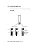
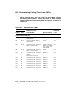
In Example B–1 the error LED on the KA65A processor in slot 1 is lit. The
reason for this is determined by examining the XCR0 and XBER registers.
The addresses for these registers are calculated by adding an offset to the
base address of the slot that contains the KA65A module. The offset for
XCR0 is 24; for XBER it is 4. (All numbers are hexadecimal.)
Description of KA65A LEDs B–7